Download
1 / 16
490 likes | 1.26k Vues
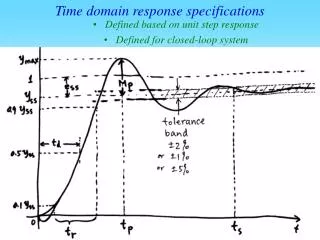
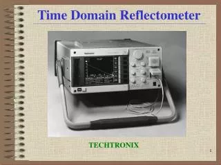
Time Domain Reflectometer. Swarthmore College Engineering 90 Aron Dobos 2 May 2006. TDR Technology Overview. Method of characterizing conductors and other test mediums by measuring energy propagation through the device under test

E N D
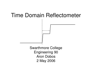
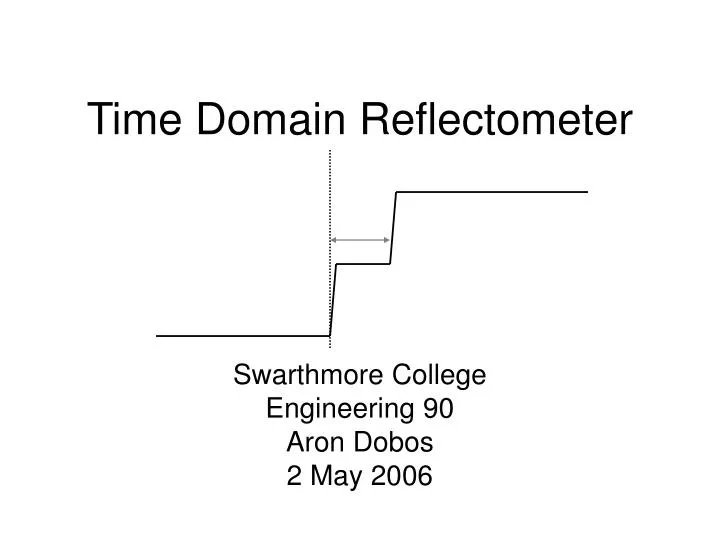
Time Domain Reflectometer Swarthmore College Engineering 90 Aron Dobos 2 May 2006
TDR Technology Overview • Method of characterizing conductors and other test mediums by measuring energy propagation through the device under test • Cable characterization, geological survey, groundwater monitoring, oil field localization, structural integrity monitoring • Project goal: TDR instrument for SMA cable characterization
Z0 ZL z = -l z = 0 Transmission Lines • Assume ideal voltage step injected at one end of transmission line with characteristic impedance Z0 • Reflection coefficient at load:
Energy Reflections • Short Circuit: Z0=0, ΓL= -1 : Pulse is reflected with unchanged magnitude but opposite polarity • Open Circuit: Z0=∞, ΓL= 1 : Pulse is reflected with same magnitude and polarity • Matched impedance ZL=Z0, ΓL= 0: No reflection
Equivalent Time Sampling • Stimulus is generated for each data point • Controlled variable time delay between stimulus to the moment the cable voltage is sampled • Energy reflections assumed to reach steady state with zero initial conditions between data points
XFRAME PRETRIGGER SPI{ PC Host Control Interface SCLK SDATA Timebase D/A 40 MHz Osc. PARALLEL INTERFACE CONV_START ADuC7026 SH_DRV A/D Sampler 62k FLASH D/A SMA0 STEP_DRV 8k SRAM POL0 POL1 Step Generator SMA1 EN0 EN1 TDR Instrument Architecture • PC-based host control software • ADuC7026 microcontroller • 2 channel step generator (EN,POL indep.) • Sampler circuit only channel 0 only
Timebase Circuit Overview • Responsible for controlling the precise synchronization between the step generator and sampling circuit • Resolution on order of 10 ps with very low jitter (< 1ps) desired • Implemented as hybrid digital/analog • Digital timer/counters in Xilinx FPGA • Analog DAC-based ramp/comparator
Timing Requirements • Purely digital method is not feasible • for 12 ps resolution, 83 GHz clock required • Purely analog solution is not feasible • Very slow ramp required giving poor jitter performance due to time-uncertainty at the comparison point • 20 MHz clock, 12-bit D/A converter, 50 ns linear ramp 12.2 ps resolution
Sampler Overview • Two stage circuit that very quickly samples the test connector voltage • Provides a proportional voltage to the microcontroller’s A/D converter • Open-loop single-ended topology
Sampler Circuit Charge injected onto C3 provides stimulus for resonant opamp circuit Monostable multivibrator opens SW1 to capture response on C4 Reset by shorting C3 via SW2 2 3 5 4 1 Amplification and offset applied to utilize A/D converter input range Differential strobe pulse opens diode bridge sampling gate briefly at time determined by timebase circuit
Stability and Linearity • Unconditionally stable due to open-loop topology • Linearity not optimal • Sampling gate reverse bias symmetry: DC midpoint value does not track input signal • Differential strobe pulse amplitude and symmetry
Testing • No test cable attached, open circuit • Z0=∞, ΓL= 1 • 3.27 ns RT • ~ 8 in / ns • ~ 13 in cable • ~ correct.
Clock Feedthrough and SNR • Significant 50 ns periodic noise
Acknowledgments • Professor Lynne Molter • Professor Erik Cheever • Ed Jaoudi • Mr. Agoston and Hyperlabs Inc. • Laszlo Dobos