Download
1 / 29
290 likes | 561 Vues
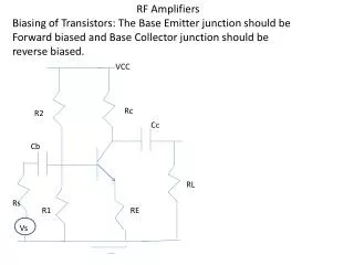
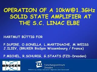
First Experience at ELBE with the new 1.3 GHz CW RF-System based on 10 kW Solid State Amplifiers. Hartmut Büttig for A.Arnold, A.Büchner, M.Justus, M.Kuntzsch, U.Lehnert, P.Michel, R.Schurig, G.Staats, J.Teichert, Radiation Source ELBE,

E N D
First Experience at ELBE with the new 1.3 GHz CW RF-System based on 10 kW Solid State Amplifiers Hartmut Büttig for A.Arnold, A.Büchner, M.Justus, M.Kuntzsch, U.Lehnert, P.Michel, R.Schurig, G.Staats, J.Teichert, Radiation Source ELBE, Helmholtz Zentrum Dresden- Rossendorf, Germany buettig@hzdr.de
1: Short Remarks on ELBE upgrade 4: 10kW@1300MHz SOLID STATE PA 5: 20 kW (Combination of two SSPA) 6: Operation of the new ELBE RF-System TOPICS
To remember where ELBE is 1
HELMHOLTZ ZENTRUM DRESDEN ROSSENDORF 800m PET Center Cancer Research How can malignant tumors be identified at an early stage and treated effectively? Radiation Source ELBE with Positrons, Neutrons, X- and Gamma Rays, Free-Electron Lasers & High-Intensity Laser 600m From Matter to Materials How does matter behave in strong fields and at small-scale dimensions? High Magnetic Field Laboratory Dresden Ion Beam Center Energy Research How can resources and energy be utilized in an efficient and safe manner? TOPFLOW Facility 1
ELBE –UPGRADE Status 3/2012 INFRARED3 – 230 µm NEUTRONS 0 – 30 MeV Ion wake field acc NEUTRONS CBS x-rays DRACO laser 150 -> 500 TW E-wake field acc. BREMSSTRAHLUNG 0 – 17 MeV XRAYS 10 – 100 keV POSITRONS 0.2 – 30 keV Penelope 1.5 PW laser APRIL 2012 3
ELBE: FUTURE CENTER OF HIGH POWER RADIATION SOURCES (HSQ) ELBE UPGRADE AFTER 10 YEARS OF OPERATION (MANY ACTIVITIES) ONE TOPIC IS: DOUBLING THE RF POWER Has an impact on: RF power amplifiers, RF - couplers, WG-windows; diagnostics, beam dumps, water cooling, mains power… UPGRADE to HSQ 3
Thermionic DC Gun 250 kV <= 260 MHz 77 pC(1mA*13MHz) ~ 500ps ~10 mm mrad RF Bunchers 260 MHz +1,3GHz compr. ~ 100:1 Linac 1,3 GHz ~20MeV@10 MeV/m <1mA CW Linac 1,3 GHz ~20 MeV@10MV/m <1mA CW SRF photo gun 9.5 MeV <= 13 MHz 80pC / 1nC / 2.5 nC ~ 5-20 ps ~ 1.5-3 mm mrad 4 x 10kW CW - VKL7811St 8 x 10kW CW-SSPA 2 2001 - 2011 Since Feb.2012
RESONANT RING (CWRF-2008): - Conditioning of RF couplers, WG-windows, (NIM A 612 (2010) 427 – 437) ELBE-UPGRADE: RF RELATED ACTIVITIES • DOUBLING THE RF – POWER: • Test of a 16 kW IOT at a SC-Cavity (2008), • (Good cooperation with Bruker BioSpin+CPI) • (SRF 2009, TUPP026) • Test of a 10 kW BRUKER SSPA (CWRF-2010)
What kind of RF-Power Amplifier for 20 kW CW@1.3GHz? • 2 Klystrons ? (1998: VKL7811St (CPI) 38 000 USD/piece) • (2008: 122 000 USD/piece) • Answer: NO • IOT ? eventually Year 2008: Start of cooperation with BRUKER BioSpin ! 3
Test in 2008 with beam in principle ok Compared with a 10kW VKL7811St Klystron (permanent magnet system) IOT is more exp. Solid state technology becomes more and more competitive. (costs: 10…12 €/W@1.3GHz) The „border line between tube- and SSA-technology“ may be in the range of 30 kW at present, but moving up quickly Remarks on 16kW - IOT 3
ELBE was focused on IOT but not happy. INSPIRATION TO SSA-Technology by: - BRUKER EXP. ( Big SSA for Orsay) - BRUKER 1kW@1.3GHz CW IOT-drivers CWRF 2008 GENEVA The trend to solid state technology was clear ! SOLID STATE AMPLIFIER (SSA)
10kW transmitter presented at SRF Berlin October 2009 - 42U cabinet - WR650 waveguide output on top - water cooled power modules - water cooled driver - built in 24kW 28V power supply Start Development 1/2009; Prototype 9/2009 14
Each single transistor is protected by a drop-in circulator Prototype . 8 x 8 Transistors Now: 9 x 8 Transistors
GAIN and PHASE CHANGE vs POWER SUPPLY VOLTAGE sensitivity to voltage changes measured at different power levels
INPUT POWER 0,1mW 0,032mW 0,32mW 24 OVERDRIVE INTERLOCK 20 10 5 OUTPUT POWER in kW 2,5 1
SMPS PN-SOURCE PN-SSPA@8kW
RAISE TIME and FALL TIME measured at 8kW output power rise time ≈20ns fall time ≈ 60ns
Observation when the Klystron was replaced by a Solid State PA (SSA): p-Mode p-2 Mode Pickup Signal at Cavity C4 Passband of a 9-cell cavity Due to a 10 times higher RF- bandwidth of the SSA at certain circumstances (e.g. detuned cavities, high loop gain) the LLRF controller locked not only on the Pi-mode but also on (Pi-1) or / and (Pi-2). The system became instable.
Solution: Improved LLRF Controller Attenuation >-70dB at Pi-1; -60dB at Pi-2 • Redesign of the LLRF-Controller • Loop filters with notches in both loops (amplitude, phase) • Loop gain is now adjustable independently from the • transfere function of the loop filters • Result: absolutely stable operation at all circumstances
Routine OP : 08.Feb. 2010 to 17.Dez.2011 No failures, much smoother than klystron op Regimes of operation: CW (FEL, Cavity C4: 8MV/m/ 0.7 mA ) - Raise-/Fall time sufficient to run macropulse mode (0.1ms/40ms) Ok for single pulse mode Pulse Mode (cavity training) TEST OPERATION AT ELBE
TIME TABLE (RF-UPGADE) • Feb. 2010: Test-Operation at ELBE (one klystron replaced) • Decision in May 2010: • we keep the replacement, SSPA is more stable than klystron, • Dec.2010: Order of another 9 Bruker SSPA • ELBE shutdown 2010/2011: Reconstruction of coolingsystem • Sep.2011 to Dec.2011: Delivery of 9 SSPA • 17.Dec.2011: Begin ELBE shutdown, all klystrons removed, • Jan. 2012: complete new installation of the power RF system • 1-st week in Feb.2012: test with dummy load, matching • 4-th week in Feb.2011. start routine OP of ELBE with SSPA
CAVITIES 1 – 4 DRIVEN BY A PAIR OF 10kW BRUKER SSPA SRF-GUN with one 10 kW SSPA FEBRUARY 2012
Block Diagram RF-POWER ( 1dB reserve below -1dB comp.: +71 dBm = 12,6 kW (LIMIT: (each amp.8,5 kW): 72,3dBm-0,3dB= 15,58 kW Waveguide Splitter (-0,2dB) Koax-Splitter (-0,5dB) Dummyload SSA LLRF Phase Bal. (-0,1dB) SSA Amp. Bal. CIRCULATOR 0 dBm +73,7 dBm +74dBm = 25 kW MATCHING PROCEDURE IS SIMPEL !
20 kW @1,3 GHz CW RF System with SSPA: Compact system (turn-key solution) High redundancy ! If the klystron fails, the accelerator stops, if a transistor fails, tjhere is no problem to continue operation ! SSPA technology is developing fast , there is no vacuum device, no time-limiting cathod, For ELBE UPGRADE: we saved about 40 % costs against tubes Summary
IPAC 2014 DRESDEN