Download
1 / 20
200 likes | 374 Vues
EE 445S Real-Time Digital Signal Processing Lab Fall 2011. Lab #2 Generating a Sine Wave Using the Hardware & Software Tools for the TI TMS320C6748 DSP Debarati Kundu. Outline. Sine Wave Generation Function Call Lookup Table Difference Equation Outputting Methods Polling Interrupts.

E N D
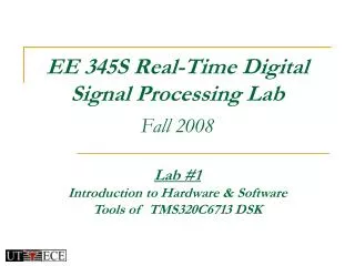
EE 445S Real-Time Digital Signal Processing LabFall 2011 Lab #2Generating a Sine Wave Using the Hardware & Software Tools for the TI TMS320C6748 DSPDebarati Kundu
Outline • Sine Wave Generation • Function Call • Lookup Table • Difference Equation • Outputting Methods • Polling • Interrupts
Sine Wave Generation • One-sided discrete-time signal of frequency ω0 cos(ω0n)u[n] • One-sided continuous-time signal of frequency ω0 cos(2πf0t)u(t) Using a sample frequency fssuch that fs > 2.f0 Substitute t=nTs=n/fs cos(2π(f0/fs)n)u[n] ω0=2π(f0/fs) radians/sample
Sine Wave Generation • Function Call: Use the C library function sin(x) whenever a sine value is needed, approximated as the ratio of 2 10th order polynomials in x • Computation: 21 multiplications, 21 additions and 1 division • Memory Usage: 22 coefficients and 1 intermediate variable (x) and one constant (2) • Lookup Table: Pre-compute and store one period of samples, can even store one-half or one-quarter period and use symmetry. • Frequency is ω0=2πN/L • L is the period • Interpolate stored values to get result at all frequencies • No computation needed, just memory reads.
Sine Wave Generation • Difference Equation: Input x[n] and output y[n] (zero IC’s) y[n] = (2 cos 0) y[n-1] - y[n-2] + x[n] - (cos 0) x[n-1] • Results from z-transform of cos(ω0n)u[n] • Computation: 2 multiplications and 3 additions • Memory Usage: 2 coefficients, 2 previous values of y[n] and 1 previous value of x[n] • Drawback is the build-up of error due to feedback
Outputting Methods • Polling: means constantly monitoring a device, a flag or a register until its value changes. • Interrupts • Enhanced Direct Memory Access 3
McASP CPU SR12 Poll RRDY ADC READ SR12 DATA AIC3106 Audio Codec Poll XRDY DAC WRITE SR11 SR11 Polling: • Poll XRDY (transmit ready) bit of the McASP(Multi-Channel Audio Serial Port) • until TRUE then write to XBUF11 register of the McASP. • If XRDY is TRUE, function returns the sample and the value 1, • If XRDY is FALSE, function returns immediately without sending a sample and • return the value 0. 4
Outputting Methods • Polling: for ( ; ; ) // Infinite Loop { x_left = scale*sin(angle_left); x_right = scale*sin(angle_right); // Increment phase angles of sine waves angle_left += delta_left; angle_right += delta_right; // Reduce angles modulo 2 pi so no overflow if (angle_left > 2.0*PI) angle_left -= 2.0*PI; if (angle_right > 2.0*PI) angle_right -= 2.0*PI; WriteSample( x_left, x_right ); } Multiply the sin() by a scale so that it doesn’t become 0 when it’s converted to integer since |sin()|<1 and floats less 1 are converted to 0
Outputting Methods • Polling: void WriteSample( float left, float right) { int32_t ileft = (int32_t) left; int32_t iright = (int32_t)right; int32_t dataOut32; /* Combine ileft and iright into a 32-bit word */ dataOut32 = (iright << 16) | (ileft & 0x0000ffff); /* Polls the Ready flag of the serial port and returns true/false to indicate success. */ while (!CHKBIT(MCASP->SRCTL11, XRDY)) {} MCASP->XBUF11 = dataOut32; } Convert float to integer Combine both samples into a 32-bit word to transmit via McASP Poll SRCTL11 bit and write output to McASP
Questions: • How does the McASP get data from the AIC? • Why replace polling with an interrupt? • When would an interrupt likely be triggered? • How do you configure an HWI in BIOS? • Under what conditions will an INT make it to the CPU? • Should we buffer the data?
Outputting Methods • Polling: • Most of the time in the polling method is spent in the infinite loop waiting for the XRDY flag to get set, • DSP is doing nothing, • A more efficient approach is to let DSP run tasks in background (modulating/demodulating, coding/decoding…), • So, serial port will interrupt background tasks when sample is received and needs to be transmitted.
Outputting Methods • Interrupts: are signals from hardware/software indicating the need for attention or change of execution. • C6748 DSP has a vectored priority interrupt controller that can handle 16 different interrupts: • RESET interrupt has highest priority, cannot be masked, • NMI (Non-Maskable Interrupt) has the second highest priority (used to notify DSP of serious hardware errors), • 2 reserved maskable interrupts come next, • 12 additional maskable interrupts (INT4-INT15) have the lowest priority.
McASP Block Diagram CPU XRBUF R-FMT XRSR AXR0 CFG BUS X-FMT SRCTL AXRn EDMA Serializer (xmt or rcv) CLKR CLK Mgmt CLKX McASPControl Registers FSR FSX • McASP can have up to 16 serializers(can be xmt or rcv – unidirectional) • Word lengths: 8, 12, 16, 20, 24, 28, 32 • All reads/writes are 32 bits • Format: mask, pad, rotate, bit-reverse • Our app: 16-bit word, ROR 16, I2S (1-bit delay), 2 serializers 6
CPU Interrupts from McASP CPU CODEC XRBUF12 XRSR RDATA=1 “Ready to Read” McASP0_INT XRBUF11 XRSR XDATA=1 “Ready to Write” • RCV/XMT INTs combined into one interrupt:MCASP0_INT • RDATA triggers when XRBUF12 is filled (32 bits) • XDATA triggers when XRBUF11 is emptied (32 bits) • Warning: underrun on XMT? McASP dies… ! 7
… How do Interrupts Work? 1. An interrupt occurs 2. Interrupt Selector 3. Sets flag in Interrupt Flag Register (IFR) • EDMA • McASP • Timer • Ext’l pins 12 124+4 4. Is this specific interrupt enabled? (IER) 5. Are interrupts globally enabled? (GIE/NMIE) 6. • CPU Acknowledge • Auto hardware sequence • HWI Dispatcher (vector) • Branch to ISR 7. Interrupt Service Routine (ISR) • Context Save, ISR, Context Restore • User is responsible for setting up the following: • #2 – Interrupt Selector (choose which 12 of 128 interrupt sources to use) • #4 – Interrupt Enable Register (IER) – individually enable the proper • interrupt sources • #5 – Global Interrupt Enable (GIE/NMIE) – globally enable all interrupts • #6 – Hardware Interrupt (HWI) Dispatcher – the vector to the ISR 12
2 3 1 4 InterruptSelector IFR IER GIE 0 .. HWI4 Vector Table 0 MCASP0_INT HWI5 1 ... .. HWI15 0 127 • C6748 has 128 possible interrupt sources (but only 12 CPU interrupts) • 4-Step Programming: • Interrupt Selector – choose which of the 128 sources are • tied to the 12 CPU ints • 2. IER enable 3. GIE enable • 3. Use the HWI Dispatcher to perform context save/restore Note: NMIE must also be enabled. DSP/BIOS automatically sets NMIE=1. If DSP/BIOS is NOT used, the user must turn on both GIE and NMIE manually. 13
3-Step Example – Tie McASP0_INT to the CPU’s HWI5 1 Configure Interrupt Selector & Vector for MCASP_INT0 (Evt #61) 61 _isrAudio 2 Set the appropriate IER bit (for HWI5) IER |= (1 << 5); 3 Turn on the HWI Dispatcher(ISR context save/restore) 15
Hardware Interrupt Events So, how do you know the names of the interrupt events and their corresponding event numbers? Ref: SPRS590 (pg 200-201) – here’s an excerpt: 17
Preemption via Dispatcher Using HWI Dispatcher • Select Dispatcher tab • Click Use Dispatcher • Default Mask is Self, this means all interrupts will preempt except this one • Select another mask option, if you prefer All: Best choice if ISR is short & fast None: Dangerous Make sure ISR code is re-entrant Bitmask: Allows custom mask 20
Example Interrupt Service Routine void isrAudio(void) { float myLeft, myRight; ReadSample(&myLeft,&myRight); // Reading the data in //Please insert signal processing code here WriteSample(myLeft,myRight); //Writing the data out }