Download
1 / 24
250 likes | 399 Vues
Scalable High Performance Main Memory System Using PCM Technology. Moinuddin K. Qureshi Viji Srinivasan and Jude Rivers IBM T. J. Watson Research Center, Yorktown Heights, NY. Main Memory Capacity Wall. More cores in system More concurrency Larger working set

E N D
Scalable High Performance Main Memory System Using PCM Technology Moinuddin K. Qureshi Viji Srinivasan and Jude Rivers IBM T. J. Watson Research Center, Yorktown Heights, NY International Symposium on Computer Architecture (ISCA-2009)
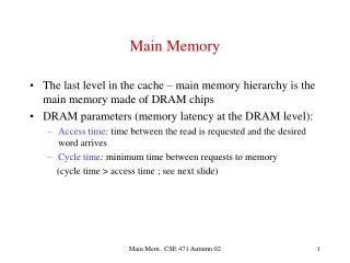
Main Memory Capacity Wall More cores in system More concurrency Larger working set Demand for main memory capacity continues to increase Main Memory System consisting of DRAM are hitting: 1. Cost wall: Major % of cost of large servers is main memory 2. Scaling wall: DRAM scaling to small technology is challenge 3. Power wall: Source: Lefurgy et al. IEEE Computer 2003 Need a practical solution to increase main-memory capacity
High-Performance Disk Memory System Flash PCM The Technology Hierarchy More capacity by cheaper, denser, (slower) technology L1(SRAM) EDRAM HDD DRAM 215 25 217 223 219 23 29 213 21 221 27 211 Typical access latency in processor cycles (@ 4 GHz) Phase Change Memory (PCM) promising candidate for large capacity main memory
Outline • Introduction • What is PCM ? • Hybrid Memory System • Evaluation • Lifetime Analysis • Summary
Bit Line Word Line Word Line N N N What is Phase Change Memory? • Phase change material (chalcogenide glass) exists in two states: • 1. Amorphous: high resistivity • 2. Crystalline: low resistivity • Materials can be switched between states • reliably, quickly, large number of times • PCM stores data in terms of resistance • Low resistance (SET state) = 1 • High resistance (RESET state) = 0 I
Large Current Small Current Memory Element RESET RESET High resistance SET Low resistance Access Device Temperature SET 106-107 W 103-104 W How does PCM work ? Tmelt Switching by heating using electrical pulses SET: sustained current to heat cell above Tcryst RESET: cell heated above Tmelt and quenched Tcryst Time [ns] Photo Courtesy: Bipin Rajendran, IBM
Key Characteristics of PCM • + Scales better than DRAM, small cell size • Prototypes as small as 3nm x 20 nm fabricated and tested [Raoux+ IBMJRD’08] • + Can store multiple bits/cell More density in the same area • Prototypes with 2 bits/cell in ISSCC’08. >2 bits/cell expected soon. • + Non-Volatile Memory Technology • Data retention of 10 years Power implications, system implications • Challenges: • More latency compared to DRAM. • Limited Endurance (~10 million writes per cell) • Write bandwidth constrained, so better to write less often.
Outline • Introduction • What is PCM ? • Hybrid Memory System • Evaluation • Lifetime Analysis • Summary
DATA W DATA T Hybrid Memory System PCM Main Memory DRAM Buffer Processor Flash Or HDD T=Tag-Store PCM Write Queue • Hybrid Memory System: • DRAM as cache to tolerate PCM Rd/Wr latency and Wr bandwidth • PCM as main-memory to provide large capacity at good cost/power
Lazy Write Architecture Problem: Double PCM writes to dirty pages on install PCM DRAM Buffer Flash/Disk Processor WRQ For example: Daxpy Kernel: Y[i] = Y[i] + X[i] Baseline has 2 writes for Y[i] and 1 for X[i] Lazy write has 1 write for Y[i] and 1 for X[i]
Average Average Num Writes to Each Line (Mln) 0 1 2 3 4 5 6 7 8 9 10 11 12 13 14 15 0 1 2 3 4 5 6 7 8 9 10 11 12 13 14 15 db1 Line_id db2 Line Level Write Back Problem: Not all lines in a dirty page are dirty Solution: Dirty bits per line in DRAM buffer and write-back only dirty lines from DRAM to PCM Problem: With LLWB, not all lines in dirty pages are written uniformly
Average Average Fine Grained Wear Leveling Solution: Fine Grained Wear Leveling (FGWL) -When a page gets allocated page is rotated by a random shift value -The rotate value remains constant while page remains in memory -On replacement of a page, a new random value is assigned for a new page -Over time, the write traffic per line becomes uniform. Num Writes to Each Line (Mln) 0 1 2 3 4 5 6 7 8 9 10 11 12 13 14 15 0 1 2 3 4 5 6 7 8 9 10 11 12 13 14 15 db2 db1 Line_id FGWL makes writes across lines in a dirty page uniform
Outline • Introduction • What is PCM ? • Hybrid Memory System • Evaluation • Lifetime Analysis • Summary
Evaluation Framework Trace Driven Simulator: 16-core system (simple core), 8GB DRAM main-memory at 320 cycles HDD (2 ms) with Flash (32 us) with Flash hit-rate of 99% Workloads: Database workloads & Data parallel kernels 1. Database workloads: db1 and db2 2. Unix utilities: qsort and binary search 3. Data Mining : K-means and Gauss Seidal 4. Streaming: DAXPY and Vector Dot Product Assumption: PCM 4X denser & 4X slower than DRAM 32GB @ 1280 cycle read latency
Reduction in Page Faults Benefit from capacity Need >16GB Streaming
Impact on Execution Time PCM with DRAM buffer performs similar to equal capacity DRAM storage
Impact of PCM Latency DRAM-8GB HYBRID (1+32)GB PCM-32GB DRAM-32GB Hybrid memory system is relatively insensitive to PCM Latency
Power Evaluations Significant Power and Energy savings with PCM based hybrid memory system
Outline • Introduction • What is PCM ? • Hybrid Memory System • Evaluation • Lifetime Analysis • Summary
For a 4GHz System, a 32GB PCM written at 1 Byte per Cycle Y = (S/B). Wmax F.225 Y = Wmax 4 million Impact of Write Endurance B Bytes/Cycle written to PCM S PCM capacity in bytes Wmax Max writes per PCM cell Assuming uniform writes to PCM Endurance (in cycles) = (S/B).Wmax F Frequency of System (4GHz) Y = Number of years (lifetime) There are 225 seconds in a year Num. cycles in Y years = Y. F.225 If Wmax = 10 million, PCM will last for 2.5 years
Lifetime Results Table shows average bytes per cycle written to PCM and Average lifetime of PCM assuming Wmax = 10 million Proposed filtering techniques reduce write traffic to PCM by 3.2X, increasing its lifetime from 3 to 9.7 years
Outline • Introduction • What is PCM ? • Hybrid Memory System • Evaluation • Lifetime Analysis • Summary
Summary • Need more main memory capacity: DRAM hitting power, cost, scaling wall • PCM is an emerging technology – 4x denser than DRAM but with slower access time and limited write endurance • We propose a Hybrid Memory System (DRAM+PCM) that provides significant power and performance benefits • Proposed write filtering techniques reduce writes by 3x and increase PCM lifetime from 3 years to 9 years Not touched in this talk but important: Exploiting non-volatile memories for system enhancement & related OS issues.