Download
1 / 15
1.05k likes | 1.92k Vues
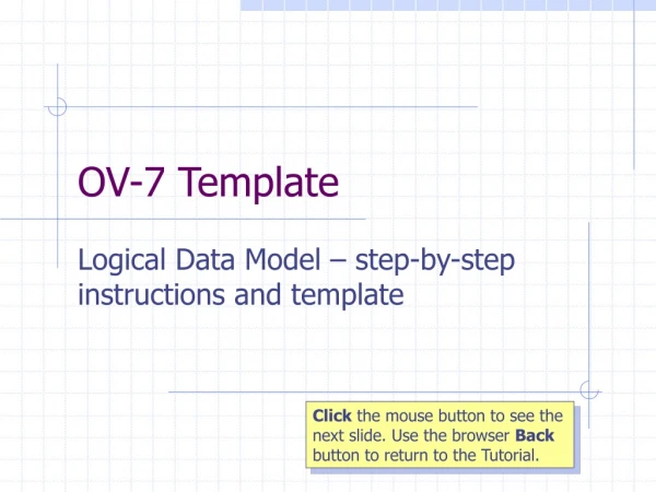
OV-1 Template. High-level Operational Concept Graphic – step-by-step instructions and templates. Click the mouse button to see the next slide. Use the browser Back button to return to the Tutorial. Four Steps in developing your OV-1 Step 1 - Identify the product's timescale.

E N D
OV-1 Template High-level Operational Concept Graphic – step-by-step instructions and templates Click the mouse button to see the next slide. Use the browser Back button to return to the Tutorial.
Four Steps in developing your OV-1Step 1 - Identify the product's timescale • Decide on the timescale this product is expected to represent (as-is, to-be, transitional) • Multiple timescales are often needed for each product; a separate OV-1 should be produced for each timescale that is needed
Step 2 - Identify contents of High-level Operational Concept Graphic • Identify the environment in which architecture resides • Determine key aspects or dimensions of the architecture's environment. Environmental characteristics vary widely depending upon the architecture's scope and objective, but they typically include reference to missions or operations, geographic distribution of assets and recognition of boundaries
Step 2 - Identify contents of High-level Operational Concept Graphic, continued… • Identify the architecture's high level components • Determine classes of participants in the architectures. Typically, these classes include entities such as organisations and resources as well as tasks, operations and missions
Step 2 - Identify contents of High-level Operational Concept Graphic, continued… • Identify the actions of, and/or relationships between high level components • Determine the relationships that exist between the high level components. Relationships can represent simple connectivity, or they may imply activities or exchanges between components (for example, messages or transactions)
Step 3 - Illustrate contents of High-level Operational Concept Graphic • Illustrate the environment in which the architecture resides • Graphically portray key aspects of the architecture's environment. Typically, such illustrations constitute the "backdrop" of a diagram. For example, a map may be used as a background to convey geographic information. The graphical technique for conveying relevant information will vary widely depending upon the scope and intent of the architecture.
Step 3 - Illustrate contents of High-level Operational Concept Graphic, continued… • Illustrate the high level components as icons • Graphically portray the key high-level components with symbols or icons. For example, an aircraft icon can be used to represent a particular type of aircraft, or a particular air organisation, or the air assets of a Joint Task Force
Step 3 - Illustrate contents of High-level Operational Concept Graphic, continued… • Illustrate the high level actions and/or relationships as line types • Connect high level components (represented as icons) with lines to convey important relationships and interactions. Depending upon the architecture's objectives, the connecting lines can be used to show simple connectivity, or they can be annotated to show what information is exchanged between the components
Templates • Two example templates have been provided following this slide – please amend or add to as necessary • In addition, 5 clip art sets are available to download from the main Tutorial page • These contain numerous Spatial, C3, Navy, Army and Air Force symbols • When you have completed your OV-1, see the slides at the end for Step 4 – the update of your Integrated Dictionary (CV-2) based on the OV-1 symbols and icons
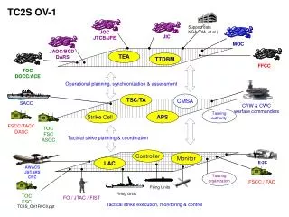
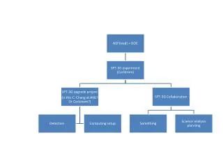
CLASSIFICATION C-130 SP-3C AP-3C Fixed Network JTFHQ CAV REGT COCS AOCS RF-111 INT BN Insert Name here INF INF AAVN FFG/FFH Submarine OTHR OV-1 Architecture Name – Template Example 1 Patrol Boats
CLASSIFICATION Fixed Network DISCON SEC BRS RES BRS AOCS COCS PSTN C3 SOC AST Name HQAST SPT ELEMENTS Name NCAST LCAST ACAST HQAST Base elm Special Forces Name INT elm SPTCOMD elm OTHR RCC Name Name OV-1 Architecture Name – Template Example 2 MOBILE STATIC Air Elements Maritime Elements Land Elements SF Base elm
Step 4 - Update your Integrated Dictionary • When you have completed your High-level Operational Concept Graphic, the following types of information should be entered into your Integrated Dictionary (CV-2) • For the graphic as a whole: mission information (name, operations type and whether joint, coalition or service specific); and geographic information (location specific or generic)
Step 4 - Update your Integrated Dictionary, continued… • For each organisational name or icon in the graphic: organisation name, general purpose of the organisation, and military service and code/symbol; role of the organisation in the mission; association of the organisation with the assets of the mission • For each asset icon in the graphic: asset name; description of the asset type represented; description of the asset's role in the mission; location information (this may be generic, such as land-based unit)
Step 4 - Update your Integrated Dictionary, continued… • For each target area indicated on the graphic: target area designation; type of target (such as airstrip, troops, aircraft); description of target importance; location information (may be generic depending on target type) • For each communications connection depicted on the graphic: connector designation; type and description of communications represented; type of information carried; assets or organisations connected
Step 4 - Update your Integrated Dictionary, continued… And finally, • For each trajectory represented on the graphic: trajectory designator; type (such as class of fire) and description of the trajectory (including weapons type, if known); asset and target involved • You can now delete the instruction slides from this presentation and save the remaining OV-1 graphics slides alone