Download
1 / 28
300 likes | 662 Vues
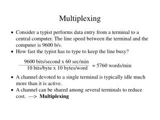
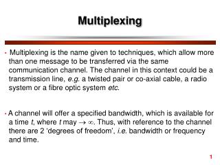
Multiplexing. Rong Wang CGS3285 Spring2004. RECOMMENDED READING. From textbooks: Page 103-111 of Data Communications: From Basics to Broadband , 3rd Edition by William J. Beyda (ISBN: 0-13-096139-6)

E N D
Multiplexing Rong Wang CGS3285 Spring2004
RECOMMENDED READING • From textbooks: • Page 103-111 of Data Communications: From Basics to Broadband, 3rd Edition by William J. Beyda (ISBN: 0-13-096139-6) • Chapter 6 of Data Communications and Networking, 3rd Edition, Behrouz A. Forouzan (ISBN: 0-07-251584-8)
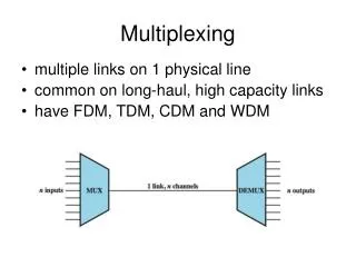
DIVIDING A LINK INTO CHANNELS • Multiplexing • A set of techniques that allows the simultaneous transmission of multiple signals across a single data link. • Multiplexer (MUX) • Combines multiple streams into a single stream (many to one). • Demultiplexer (DEMUX) • Separates the stream back into its component transmission (one to many) and directs them to their correct lines.
TIME DIVISION MULTIPLEXING (TDM) • Digital process that allows several connections to share the high bandwidth of a link • Time Slots and Frames • Each terminal/host given a “slice” of time (time slot) • In TDM, a frame consists of one complete cycle of time slots, with one slot dedicated to each sending device.
TDM FRAMES • Pure TDM: mux-to-mux speed = aggregate terminal speeds • No loss of data (similar to voice call multiplexing)
Example 1 Four 1-Kbps connections are multiplexed together. A unit is 1 bit. Find (1) the duration of 1 bit before multiplexing, (2) the transmission rate of the link, (3) the duration of a time slot, and (4) the duration of a frame? Solution We can answer the questions as follows: 1. The duration of 1 bit is 1/1 Kbps, or 0.001 s (1 ms). 2. The rate of the link is 4 Kbps. 3. The duration of each time slot 1/4 ms or 250 ms. 4. The duration of a frame 1 ms.
INTERLEAVING • Multiplexer/Demultiplexer process a terminal/host’s unit in turn • Character (byte) Interleaving • Multiplexing perform one/more character(s) or byte(s) at a time (one byte per unit) • Bit Interleaving • Multiplexing perform on one bit at a time (one bit per unit)
Example 2 Four channels are multiplexed using TDM. If each channel sends 100 bytes/s and we multiplex 1 byte per channel, show the frame traveling on the link, the size of the frame, the duration of a frame, the frame rate, and the bit rate for the link. Solution
Example 3 A multiplexer combines four 100-Kbps channels using a time slot of 2 bits. Show the output with four arbitrary inputs. What is the frame rate? What is the frame duration? What is the bit rate? What is the bit duration? Solution
SYNCHRONIZING • One or more Framing bit (s) is (are) added to each frame for synchronization between the multiplexer and demultiplxer • If 1 framing bit per frame, framing bits are alternating between 0 and 1
Example 4 We have four sources, each creating 250 characters per second. If the interleaved unit is a character and 1 synchronizing bit is added to each frame, find (1) the data rate of each source, (2) the duration of each character in each source, (3) the frame rate, (4) the duration of each frame, (5) the number of bits in each frame, and (6) the data rate of the link. Solution See next slide.
Solution (continued) We can answer the questions as follows: 1. The data rate of each source is 2000 bps = 2 Kbps. 2. The duration of a character is 1/250 s, or 4 ms. 3. The link needs to send 250 frames per second. 4. The duration of each frame is 1/250 s, or 4 ms. 5. Each frame is 4 x 8 + 1 = 33 bits. 6. The data rate of the link is 250 x 33, or 8250 bps.
Example 5 Two channels, one with a bit rate of 100 Kbps and another with a bit rate of 200 Kbps, are to be multiplexed. How this can be achieved? What is the frame rate? What is the frame duration? What is the bit rate of the link? Solution We can allocate one slot to the first channel and two slots to the second channel. Each frame carries 3 bits. The frame rate is 100,000 frames per second because it carries 1 bit from the first channel. The frame duration is 1/100,000 s, or 10 us. The bit rate is 100,000 frames/s x 3 bits/frame, or 300 Kbps.
STATISTICAL TDM (STDM) • Mux-to-Mux speed < aggregate terminal/host speeds • Time slots allocated based on traffic patterns • uses statistics to determine allocation among users • must send port address with data (takes additional time slots) • May Potential loss of data during peak periods • may use data buffering and/or flow control to reduce loss • Not always transparent to user terminals and host/FEP • delays and data loss possible • So why use a stat mux? • more economical - need fewer muxes, cheaper lines • more efficient - allows more terminals to share same line • OK to use in many situations (e.g., terminal users
FREQUENCY DIVISION MULTIPLEXING (FDM) • Assigns different analog frequencies to each connected device • Like Pure TDM, • mux-to-mux speed = aggregate terminal speeds • No loss of data so transparent to users and host/FEP • Channels must be separated by strips of unused bandwidth - guard bandwidth
FDM PORCESS • Signals of each channel are modulated onto different carrier signal • The resulting modulated signals are then combined into a single composite signal that is sent out over a media link • The link should have enough bandwidth to accommodate it
FDM DEMULTIPLEXING • Demultiplexer uses a series of filters to decompose the multiplexed signal into its constituent component signals • The individual signals are then passed to a demodulator that separates them from their carriers and passes them to the waiting receivers
Example 6 Assume that a voice channel occupies a bandwidth of 4 KHz. We need to combine three voice channels into a link with a bandwidth of 12 KHz, from 20 to 32 KHz. Show the configuration using the frequency domain without the use of guard bands. Solution Shift (modulate) each of the three voice channels to a different bandwidth, as shown in Figure of next slide.
Example 7 Five channels, each with a 100-KHz bandwidth, are to be multiplexed together. What is the minimum bandwidth of the link if there is a need for a guard band of 10 KHz between the channels to prevent interference? Solution For five channels, we need at least four guard bands. This means that the required bandwidth is at least 5 x 100 + 4 x 10 = 540 KHz, as shown in Figure of following slide.
WAVE DIVISION MULTIPLEXING (WDM) • An analog multiplexing technique to combine optical signals • Multiple beams of light at different frequency • Carried by optical fibber • A form of FDM • Each color of light (wavelength) carries separate data channel • Commercial systems of 160 channels of 10 Gbps now available