Download
1 / 37

E N D
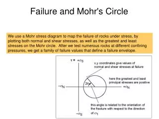
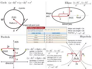
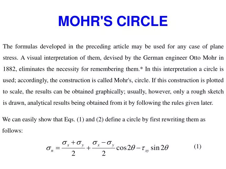
MOHR'S CIRCLE The formulas developed in the preceding article may be used for any case of plane stress. A visual interpretation of them, devised by the German engineer Otto Mohr in 1882, eliminates the necessity for remembering them.* In this interpretation a circle is used; accordingly, the construction is called Mohr's, circle. If this construction is plotted to scale, the results can be obtained graphically; usually, however, only a rough sketch is drawn, analytical results being obtained from it by following the rules given later. We can easily show that Eqs. (1) and (2) define a circle by first rewriting them as follows: (1)
(2) Rewriting the equation (1) (3) Taking squares of equations (2) & (3) (4) (5)
By adding equ.(4) & (5), and simplifying, we obtain (6) Recall that σx, σy, and τxy are known constants defining the specified state of stress, whereas σn and τare variables. Consequently, (σx + σy)/2 is a constant, say, h, and the right-hand member of Eq. (6) is another constant, say, r. Using these substitutions, we transform Eq. (6) into (7)
Center of circle is From the origin. Figure 9-14 represents Mohr's circle for the state of plane stress that was analyzed in the preceding article. The center C is the average of the normal stresses, and the radius From figure
is the hypotenuse of the right triangle CDA. How do the coordinates of points E, F, and G compare with the expressions derived for σ1,σ2 ,τmax?We shall see that Mohr's circle is a graphic visualization of the stress variation given by Eqs. (1) and (2). The following rules summarize the construction of Mohr's circle. Figure 9-14 Mohr's circle for general state of plane stress.
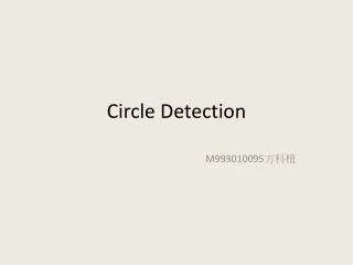
Rules for Applying Mohr's Circle to Combined Stresses 1. On rectangular σ-τ axes, plot points having the coordinates (σx, τxy) and (σy, τyx). These points represent the normal and shearing stresses acting on the x and y faces of an element for which the stresses are known. In plotting these points, assume tension as plus, compression as minus, and shearing stress as plus when its moment about the center of the element is clockwise.* 2. Join the points just plotted by a straight line. This line is the diameter of a circle whose center is on the a axis. 3. As different planes are passed through the selected point in a stressed body, the normal and shearing stress components on these planes are represented by the coordinates of points whose position shifts around the circumference of Mohr's circle.
4. The radius of the circle to any point on its circumference represents the axis directed normal to the plane whose stress components are given by the coordinates of that point. 5. The angle between the radii to selected points on Mohr's circle is twice the angle between the normal to the actual planes represented by these points, or to twice the space angularity between the planes so represented. The rotational sense of this angle corresponds to the rotational sense of the actual angle between the normal to the planes; that is, if the n axis is actually at a counterclockwise angle θ from the x axis, then on Mohr's circle the n radius is laid off at a counterclockwise angle 2θ from the x radius.
x x-axis v, v1 plane 2θs1 max σx, xy σ2 2θP2 2θP1 2θs2 σy, -xy min y σy y-axis H, H1 plane σx σ1
Example Problem 1 It has been determined that a point in a load-carrying member is subjected to the following stress condition: σx=400MPa σy=-300MPa τxy=200MPa(CW) Perform the following • Draw the initial stress element. • Draw the complete Mohr’s circle, labeling critical points. • Draw the complete principal stress element. • Draw the maximum shear stress element.
Solution The 15-step Procedure for drawing Mohr's circle is used here to complete the problem. The numerical results from steps 1-12 are summarized here and shown in Figure 11-12. Step 1. The initial stress element is shown at the upper left of Figure 11-12. Step 2. Point 1 is plotted at ax = 400 MPa and τxy = 200 MPa in quadrant 1. Step 3. Point 2 is plotted at ay = -300 MPa and τyx = -200 MPa in quadrant 3. Step 4. The line from point 1 to point 2 has been drawn. Step 5. The line from step 4 crosses the σ-axis at the average applied normal stress, called O in Fig 11-12, is computed from any,
Step 6. Point 0 is the center of the circle. The line from point O through point 1 is labeled as the x-axis to correspond with the x-axis on the initial stress element. Step 7. The values of G, b, and R are found using the triangle formed by the lines from point 0 to point 1 to σx = 400 MPa and back to point O. The lower side of the triangle,
The vertical side of the triangle, b, is completed from The radius of the circle, R, is completed from:
FIG 11-13 Results for Example Problem 11-2 the face on which the tensile stress σ1 = 453 MPa acts. The compressive stress σ2= -353 MPa acts on the faces perpendicular to the al faces. Step 14. The angle 2Φ’ is shown in Figure 11-12 drawn from the x -axis CCW to the vertical diameter that locates τmax at the top of the circle. Its value can be found in either of two ways. First using Equation 11-8 and observing that the numerator is the same as the value of a and the denominator is the same as the value of b from the construction of the circle. Then
Or, using the geometry of the circle. we can compute Then the angle Φ’ is one-half of 2Φ’. Step 15. The maximum shear stress element is drawn in Figure 11-13(c), rotated 30.13° CCW from the original x-axis to the face on which the positive τmax acts. The maximum shear stress of 403 MPa is shown on all four faces with vectors that create the two pairs of opposing couples characteristic of shear stresses on a stress element. Also shown is the tensile stress σmax = 50 MPa acting on all four faces of the element.
Summary of Results for Example Problem 1 Mohr's Circle Given σx=440MPa σy= -300MPa τxy=200MPa CW Results Figures 11-12 and 11-13. σ1=453MPa σ2= -353MPa Φ=14.87o CW from x-axis τmax=403MPa σavg=50MPa Φ’=30.13o CCW fron x-axis
Example Problem 2 Given σx=-120MPa σy= 180MPa τxy=80MPa CCW • Draw the initial stress element. • Draw the complete Mohr’s circle, labeling critical points. • Draw the complete principal stress element. • Draw the maximum shear stress element. Solution: Results Figures 11-15. σ1=200MPa σ2= -140MPa Φ=75.96o CCW τmax=170MPa σavg=30MPa Φ’=59.04o CW
Figure 11-15 Result for Example Problem 11-4, X-axis in the third quadrant.
Example Problem 3 Given σx=-30ksi σy=20 ksi τxy=40 ksi CW • Draw the initial stress element. • Draw the complete Mohr’s circle, labeling critical points. • Draw the complete principal stress element. • Draw the maximum shear stress element. Solution: Results Figures 11-5. σ1=42.17 ksi σ2= -52.17 ksi Φ=61.0o CW τmax=47.17 ksi σavg=-5.0 ksi Φ’=16.0o CW Comments The x-axis is in the fourth quadrant.
Figure 11-16 Result for Example Problem 11-5, X-axis in the fourth quadrant. Example Problem4 Given σx=220MPa σy=-120MPa τxy=0MPa Solution: Results Figures 11-17. σ1=220MPa σ2= -120MPa Φ=0o τmax=170MPa σavg=50MPa Φ’=45.0o CCW
Fig 11-17 Result for Example Problem 11-5,Special case of biaxial stress with no shear
Example Problem 5: Given σx=40 ksi σy=0 ksi τxy=0ksi • Draw the initial stress element. • Draw the complete Mohr’s circle, labeling critical points. • Draw the complete principal stress element. • Draw the maximum shear stress element. Solution: Results Figures 11-18. σ1=40 ksi σ2=0 ksi Φ=0o τmax=20 ksi σavg=20 ksi Φ’=45.0o CCW
Fig 11-18 Results of Example Problem 11-7. Special case of uniaxial tension Example Problem 6 Given σx=0 ksi σy=0 ksi τxy=40ksi CW Solution: Results Figures 11-19. σ1=40 ksi σ2=-40 ksi Φ=45o CW
τmax=40 ksi σavg=0 ksi Φ’=0o
Fig 11-19 Results of Example Problem 11-8, Special case of Pure shear.
Example Problem 7: At a certain point in a stressed body, the principal stresses are σx = 80 MPa and σy = -40 MPa. Determine σ and τ on the planes whose normal are at +30° and + 1 20° with the x axis. Show your results on a sketch of a differential element.
Solution:The given state of stress is shown in Fig. 9- 1 5a. Following the rules given previously, draw a set of rectangular axes and label them a and r as shown in Fig. 9-15b. (Note that, for convenience, the stresses are plotted in units of MPa.) Since the normal stress component on the x face is 80 MPa and the shear stress on that face is zero, these components are represented by point A which has the coordinates (80, 0). Similarly, the stress components on the y face are represented by point B (-40, 0). According to rule 2, the diameter of Mohr's circle is AB. Its center C, lying midway between A and B, is 20 MPa from the origin O. The radius of the circle is the distance CA = 80 - 20 = 60 MPa. From rule 4, the radius CA represents the x axis. In accordance with rules 4 and 5, point D represents the stress components on the face whose normal is inclined at +30° to the x axis, and point E represents the stress components on the perpendicular face. Observe that positive angles on the circle are plotted in a counterclockwise direction from the x axis and are double the angles between actual planes.
* This special rule of sign for shearing stress makes τx= —τyxin Mohr's circle. From here on, we use this rule to designate positive shearing stress. However, the mathematical theory of elasticity uses the convention that shearing stress is positive when directed in the positive coordinate direction on a positive face of an element, that is, when acting upward on the right face or rightward on the upper face. This other rule makes τxy = τyx, which is convenient for mathematical work but confusing when applied to Mohr's circle.
From rule 3, the coordinates of point D represent the required stress components on the 30° face. From the geometry of Mohr's circle, these values are On the perpendicular 120° face we have Both sets of these stress components are shown on the differential element in Fig. 9-16. Observe the clockwise and counterclockwise moments ofτand τ', respectively, relative to the center of the element (see rule 1). Finally, note that a complete sketch of a differential element shows the stress components acting on all four faces of the element and the angle at which the element is inclined.