Download
1 / 7
70 likes | 83 Vues
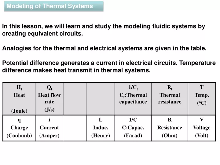
Modeling of T hermal Systems. In this lesson, we will learn and study the modeling fluidic systems by creating equivalent circuits. Analogies for the thermal and electrical systems are given in the table.

E N D
Modeling of Thermal Systems In this lesson, we will learn and study the modeling fluidic systems by creating equivalent circuits. Analogies for the thermal and electrical systems are given in the table. Potential difference generates a current in electrical circuits. Temperature difference makes heat transmit in thermal systems.
D.Rowell & D.N.Wormley, System Dynamics:An Introduction, Prentice Hall, 1997 Thermal Capacitance: Ct=mCp Ct: Thermal capacitance, Cp: Specific heat, m: Mass Thermal resistance in heat transfer by conduction : Rt:Resistance, ρc:Conduction coefficient, A:Cross section, L:Length Thermal resistance in heat transfer by convection : Ch: Convection coefficient
Qn Ta 2 1 Qk1 TB VB Qk2 o o o o Analogous Electrical Circuits of Thermal Systems Thermal systems can be analyzed by creating equivalent electrical circuits. Let’s consider Example 6.1. A thermal system is given here. We will create the equivalent electrical circuit for the system by using the analogy. Example 6.1 ThermalElec. Qk1, Qk2, TB Inputs: Rn Rn Cn Cn Tn Vn
R1B C1 R1a Q1B 1 Qk1 Va o o Q1a Thermal System In the thermal system, the room #1 is heated with the heat source Qk1. Ta s the atmospheric temperature. While the objects in the room #1 are heating depending on the their thermal capacitance, at the same time there is a heat transfer from the room #1 to the next room #B. In the equivalent circuit, the current supply qk1_dot can supply the line with the resistance R1a, capacitor C1 and the line with the resistor R1B. We remember the analogy that the heat flow, thermal capacitance, thermal resistance in thermal systems correspond to the electrical current, capacitor, resistor in electrical systems, respectively. R1a corresponds to the thermal resistance between the room #1 and atmosphere. R1B corresponds to the thermal resistance between the room #1 and room B. C1 in the circuit corresponds to the thermal capacitance of the room #2. Ta Analogous Circuit
RBa R1B C1 R1a + QB2 Q1B VB - 1 Qk1 TB Va RB2 o o Q1a Thermal System The room B has a heat source which the temperature is controlled. The value of the temperature in the room B is TB. There is a heat transfer from the room B to the room #2 or vice versa. We remember from the analogy table that a temperature in thermal systems correspond to a voltage in electrical systems. So, a voltage source VB corresponding to TB is placed into the circuit in the electrical system. This voltage source’s current q1b_dot can supply the lines with the resistance RBa and the resistance RB2. Ta Analogous Circuits
RBa R1B C2 C1 R2a R1a + Q1B QB2 VB - 2 1 Qk1 TB Va Qk2 RB2 o o o o QBa Q2a Q1a Thermal System The room #2 is heated with the heat source Qk2. There is a heat transfer between the room #2 and the atmosphere. In the equivalent circuit, the current supply qk2_dot can supply the line with the resistance R2a, capacitor C2 and the line with the resistor RB2. C2 in the circuit corresponds to the thermal capacitance of the room #2. The heat sources Qk1, Qk2 and the controlled temperature TB are the inputs of the thermal system. The currents qk1_dot, qk2_dot and the voltage source VB are the inputs of the electrical system. Ta Analogous Electrical Circuits
CAD-CAE Dynamic (Transient) behaviour Steady-state behaviour By analyzing the equivalent circuit, transient or steady-state dynamic behavior at a desired point of a circuit can be calculated. Thus, the corresponding heat flow and temperatures at a desired point of a thermal system are found. Nowadays, thermal systems can be analyzed by the computers. Before the developments in computer technology, in order to analyze thermal systems engineers have used the equivalent circuits, which are produced easily and cheaply. Engineers have developed thermal systems by doing experiments with the circuits.