Download
1 / 36
430 likes | 825 Vues
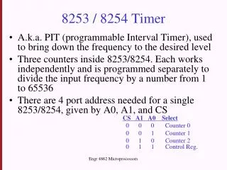
Programmable Interval Timer - 8254. Prepared By: Prof. M. B. Salunke SITS, Narhe, Pune - 41. E-mail: msalunke@gmail.com. Features. Three Independent 16-Bit Counters, Clock input upto 10 MHz, Status Read-Back Command, Six Programmable Counter Modes, Binary or BCD Counting,

E N D
Programmable Interval Timer - 8254 Prepared By:Prof. M. B. SalunkeSITS, Narhe, Pune - 41. E-mail: msalunke@gmail.com
Features • Three Independent 16-Bit Counters, • Clock input upto 10 MHz, • Status Read-Back Command, • Six Programmable Counter Modes, • Binary or BCD Counting, • Single +5V Supply, • Superset of PIT-8253.
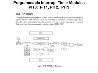
Internal Blocks of Counter • Count Register (CR) to store count (CRL & CRM), • Counting elements (CE) are used for counting, • Output Latch (OLL & OLM) to latch the count in CE, • The Control Word Register is not part of the Counter itself, but its contents determine how the Counter operates. • The status register, when latched, contains the current contents of the Control Word Register and status of the output and null count flag.
8254 Programming Each counter is individually programmed by writing a control word, followed by the initial count. The control word allows the programmer to select the counter, mode of operation, binary or BCD count and type of operation (read/write). Control Word format
WRITE Operation • Control Word to Control register • Initial count must follow the count format specified in the Control Word (least significant byte only, most significant byte only, or least significant byte and then most significant byte).
READ Operation Three Possible Methods to read counters • Simple Read Operation, • Counter Latch Command, • Read Back Command. Note: Two I/O read operations have to be performed to get first Lower Byte and then higher byte of count.
Simple Read Operation: After inhibiting counter using GATE or CLK input we can read count Counter Latch Command: D5 D4 = 0 0 Designates the counter latch command SC1 SC2 = Specify counter to be latched. X – Don’t care bits must be 0 to ensure compatibility with future Intel products.
Interleaved Read and Write Operations: Valid sequence for read and write of the same counter set for two byte count: • Read least significant byte, • Write new least significant byte, • Read most significant byte, • Write new most significant byte.
Modes of 8254 Six Different Modes • Mode 0: Interrupt On Terminal Count • Mode 1: Hardware Retriggerable One-shot • Mode 2: Rate Generator • Mode 3: Square Wave Mode • Mode 4: Software Triggered Strobe • Mode 5: Hardware Triggered Strobe (Retriggerable)
MODE 0 – Interrupt on Terminal Count N : Undefined Count
Applications of 8254 • Real time clock • Event-counter • Digital one-shot • Programmable rate generator • Square wave generator • Binary rate multiplier • Complex waveform generator • Complex motor controller
References • Microprocessors and Interfacing by Douglas V. Hall, TMH Publication. • Intel 8254 data sheet (www.datasheetcatalog.com)