Download
1 / 40
420 likes | 561 Vues
Materials Science in MEMS. GSA: Brooks A. Gross 06.29.2006. Lecture Outline. Silicon-Compatible Material System Other Materials and Substrates Important Material Properties & Physical Effects. Silicon-Compatible Material System. Silicon (Chemical symbol: Si)

E N D
Materials Science in MEMS GSA: Brooks A. Gross 06.29.2006
Lecture Outline • Silicon-Compatible Material System • Other Materials and Substrates • Important Material Properties & Physical Effects
Silicon-Compatible Material System • Silicon (Chemical symbol: Si) • Economically manufactured in single-crystal substrates • Crystalline nature provides electrical & mechanical advantages • Electrical conductivity modulated by impurity doping (key to electronic semiconductor devices) • Mechanically, it is elastic and robust • A suitable material platform for integrating electronic, mechanical, thermal, optical, and microfluidic functions
Low Cost of Si • $10 for 100-mm-diameter wafer • $15 for 150-mm-diameter wafer
Structural Types of Si • Crystalline • Polycrystalline (aka - polysilicon or poly-Si) • Amorphous • The latter 2 are usually deposited as thin films typically under 5μm thick.
Si Wafers • Commercially available as circular wafers • Sizes: 100, 150, 200, & 300mm diameter • Over 0.5mm thick (double-sided polished wafers usually 100 microns thinner) • Anything above 150mm is not economical for MEMS at this time. • Why? • Fabrication facility costs for new machines are prohibitive when the machines are the newest on the market for the IC industry. • It’s all about production volume.
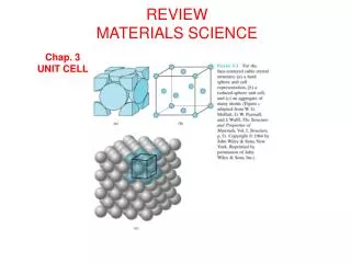
Crystal structure of Si • Diamond-cubic • Can be discussed as simple cubic • Primitive unit (smallest repeating block) of Si • 3 major axes called principle axes • Reference axes using a notation called Miller indices
Miller indices • Directions specified by brackets [xyz] for the axes (x,y,z) • No commas between numbers • Negative #’s have a line over them instead of a minus sign • Groups of directions specified with carets (e.g. <100>: [100] = +x,[010] = +y,[001] = +z, & their negative counterparts) • (xyz) specify a plane perpendicular to a vector • {xyz} specify all equivalent planes. • What the heck?
Angles Between Planes • {100} & {110} planes have 45O or 90O angles between them • {100} & {111} planes have 54.7O or 125.3O angles between them • {111} & {110} planes have 35.3O, 90O or 144.7O angles between them
Why are angles of intersection important? • Direction-specific etchants (Ch. 3) • Takes advantage of the crystal lattice to for different structures of the MEMS • Important to start with the best wafer type for a given process to yield the MEMS with the least amount of steps • Saves time and $!!! • How do you know which type of wafer you have?
Crystalline Si Characteristics • Hard & brittle • Tensile yield strength = 7GPa • Young’s modulus = 169GPa in <110>, 130GPa in <100> (similar to steel) • Good thermal conductivity • Not optically active (so no lasers) • Consistent across wafer lots, making bulk processing reliable
Poly-Si • Used to: • make micromechanical structures • integrate electrical interconnects, thermocouples, p-n junction diodes, etc. • Mechanical properties • Vary with deposition conditions, but similar to crystalline Si (except for temperature: Si stable up to 700O C, poly-Si up to 250O C) • Important to control conditions so that mechanical structures like beams do not curl
Silicon Oxide • Si oxidizes on the surface when exposed to oxygen. • At room T, self-limited to a few nm • Inert, acting as a protective layer against chemicals • Great electrical & thermal insulators • Can be used as a sacrificial layer (Ch. 3) • Can be formed on the Si using various techniques (Ch. 3) • Drawback is large intrinsic stress, which can be hard to control in the manufacturing process
Silicon Nitrides (SiXNY) • Insulating film • Barrier to ion diffusion (e.g. sodium or potassium ions in biological systems) • Young’s modulus higher than Si • Intrinsic stress can be controlled • Can be used as a masking material
Thin Metal Films • Deposited by sputtering, evaporation, CVD, and some by elecroplating • Metal chosen by considering end-use. • Some metals are used as an adhesion layer (e.g. chromium)
Polymers • Used as a photoresist or as structures of the MEMS • Thicknesses range between 1 and 100 microns • Can be used as chemical gas sensors and humidity sensors due to their unique adsorption and absorption properties
Other Materials • Glass • Can be electrostatically bonded to Si • Used in making pressure sensors • Has a different coefficient of thermal expansion than Si, resulting in interfacial stresses • Crystalline quartz • Piezoelectric
Other Materials • Si-Carbide & diamond • Very hard • High stiffness (high Young’s modulus) • resistant to harsh chemicals • Wide bandgap • Very high thermal conductivity • More in next Tuesday’s lecture…
Other Materials • Group III-V compound semiconductors • Being explored as an alternative to Si for different mechanical structures • Different orientation-dependent etching • Practical way to integrate RF switches, antennas, and other high-frequency components for wireless devices
Polymers • Long chains of carbon atoms or Si atoms (silicones) • Can be used to make microfluidic channels • Low cost • Many are flexible • Can act as barriers to flow of water or vapor
Other Materials • Shape-memory alloys • Return to a predetermined shape when heated above a transition temperature (material-dependent) • Ti-Ni most widely used • Can generate very large forces • Good for actuation purposes (unlike piezoelectric and electrostatic actuators, but they can transition much more quickly)
Piezoresistivity • Derived from Greek word piezein meaning to apply pressure • Discovered by Lord Kelvin in 1856 • Phenomenon by which an electrical resistance changes in response to a mechanical stress • First application was a metal strain gauge to measure strain, inferring force weight and pressure • Most resistance change in metals due to dimensional changes • C.S. Smith discovered in 1954 that the effect is greater in Si & germanium than in metals. • Majority of current commercial pressure sensors use Si piezoresistors
Physics of Piezoresistivity • It arises from the deformation of the energy bands as the result of an applied stress. • The deformed bands affect the effective mass and the mobility of electrons and holes, therefore modifying resistivity.
Piezoresistivity for the Engineer • The fractional change in resistivity, Δρ/ρ, is to a 1st order linearly dependent on σװ& σ┴,the 2 stress components parallel & orthogonal to the direction of the resistor, respectively. • Direction of resistance defined as that of the current flow: Δρ/ρ= πװσװ+ π┴ σ┴ • are called the parallel & perpendicular piezoresistive coefficients
Piezoresistivity of Poly & Amorphous Si • Coefficients lose their sensitivity to direction • Use a gauge factor, K, instead • From -30 to +40—about 1/3 of single-crystal Si • K decreases quickly as doping increases above 1019cm-3 • Main advantage is a reduced TCR (i.e. much lower dependence on temperature)
Piezoelectricity • Some crystals produce an electric field when subjected to an external force. • Also, they can expand or contract in response to an externally applied voltage. • Discovered in quartz by Curie brothers in 1880 • 1st practical application in 1920s as quartz-based sonar. • Why piezoelectric MEMS? • They can act as both sensors and actuators. • They can be deposited as thin layers on Si.
Piezoelectricity • At the atomic level • Charge asymmetry within the unit cell • This forms a net electric dipole. • Summation of dipoles over entire crystal gives a net polarization & an effective electric field. • If the crystal has a center of symmetry, there is no piezoelectric effect. • Curie temperature is a critical temp. specific to the material at which it loses its piezoelectric properties.
Thermoelectricity • In the absence of an electric field, there are 3 distinct thermoelectric effects: • Seebeck – used in thermocouples to measure temp. differences • Peltier – used to make thermoelectric coolers & refrigerators • Thomson – uncommon
Peltier Effect • Current flow across a junction of 2 dissimilar materials causes a heat flux, cooling one side and heating the other • Large scale appliances, like the mobile wet bar of the 1950s, have poor energy conversion efficiency. • Today, n-type & p-type bismuth telluride elements are used to cool microprocessors, laser diodes, & IR sensors. • Difficult to make thin film versions
Seebeck Effect • Temperature gradient across an element gives rise to a measurable E field that tends to oppose the charge flow resulting from the T imbalance. *Board with next slide