Download
1 / 26
260 likes | 316 Vues
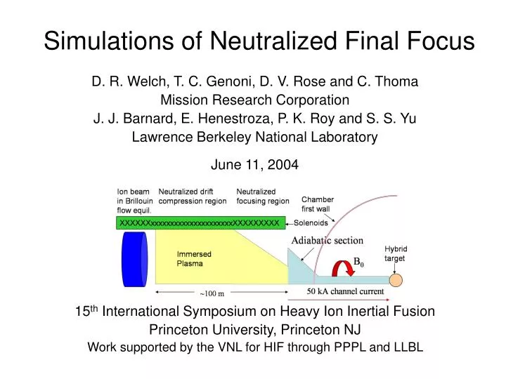
Simulations of Neutralized Final Focus. D. R. Welch, T. C. Genoni, D. V. Rose and C. Thoma Mission Research Corporation J. J. Barnard, E. Henestroza, P. K. Roy and S. S. Yu Lawrence Berkeley National Laboratory June 11, 2004 15 th International Symposium on Heavy Ion Inertial Fusion

E N D
Simulations of Neutralized Final Focus D. R. Welch, T. C. Genoni, D. V. Rose and C. Thoma Mission Research Corporation J. J. Barnard, E. Henestroza, P. K. Roy and S. S. Yu Lawrence Berkeley National Laboratory June 11, 2004 15th International Symposium on Heavy Ion Inertial Fusion Princeton University, Princeton NJ Work supported by the VNL for HIF through PPPL and LLBL
Higher perveance beams possible with a modular solenoid driver* require neutralization to compress and focus • Beam, plasma requirements for longitudinal compression in a plasma • Beam-plasma instabilities • Transition from Brillouin Flow (BF) to Neutralized Drift Compression (NDC) • Transverse focusing in an immersed plasma • Final Focus design for HIF driver • NDC experiments with proposed NTX upgrade We examine NDC transport issues, transition, final focus and integrated transport *See W.I-12 Ed Lee
LSP is used to examine in some depth NDC instability and transport issues With plasma plug and RF Plasma With plasma plug 100% neutralization NTX* MEASUREMENT 6-mA, 254-keV, 2-cm K+ beam, with L = 1m With plasma plug and RF Plasma With plasma plug 100% neutralization LSP SIMULATIONS LSP is being benchmarked in plasma neutralization experiments on NTX *See Th.I-5 P. Roy
Required beam velocity tilt, accuracy • velocity tilt for compression at position L • L increases with initial pulse length tp , 1/tilt • tmin is the minimum pulse time for error v/v e.g., 230 MeV, 210 ns Ne+ beam with 105-m drift length requires a 10% velocity tilt, 8 ns pulse requires v/v < .36%
Plasma neutralization must be excellent The beam axial impulse due to space charge over the neutralized drift, EL/<v>, must be less than the applied velocity tilt. The neutralization fraction where K(0) is the initial beam perveance defined as K = 2Ib/IA2 with Alfven current IA = mic3/eZ. plasma plug and RF plasma e.g. 780 A, 230 MeV, 20-cm radius, K(0) = 4x10⁻⁴ Ne+ beam with L = 105 m, then f > 0.995 Consistent with NTX spot size measurements for plasma neutralization of scaled beam
1D simulations of neutralization and impact of two-stream instability • 780-A, 110-ns, 20-cm Ne+ beam with L = 5450 cm • 10% v tilt, random beam velocity variation .1% • nb = 109 cm-3 uniform np = 6x10⁸ - 4x1010 cm-3 • z = ½ c / p , t = 1/5p for all sims 200 ns 1200 ns The most the beam can focus to is 40 kA due to the .1% velocity variation (50x compression) Snapshots of beam phase space early and just before focus for ballistic transport showing effect of applied velocity variation
ballistic4.0x1010 cm-31.0x1010 cm-32.5x109 cm-3 6.0x108 cm-3 ballistic4.0x1010 cm-31.0x1010 cm-32.5x109 cm-3 6.0x108 cm-3 Beam neutralization improves with plasma density • L p /c > 5000 , tp p > 1000 for 4x1010 cm-3 plasma density • Poor global neutralization at small plasma density limits pulse length • Effect of 2 stream on beam is weak, produces longitudinal wings Beam current at focus Axial field near focus
Two-stream impact on phase space 2.5x109 cm-3 density plasma Ballistic transport Too low a density results in space charge spreading Saturation of two stream growth leads to tolerable momentum spread 1.0x1010 cm-3 density plasma 4x1010 cm-3 density plasma
Solenoidal field reduces growth rate of beam filamentation • Example: Focusing 150 kA, 230 MeV Ne+ “combined” annular beam (K = 0.14) in plasma • Small but finite and nonlinear magnetic fields lead to beam filamentation, emittance growth • np >> nb and rc/sd < 1 yield best transport in LSP simulations and theory (W.P-14 I. Kaganovich) Uniform 10-cm beam
Beam matching possible from Brillouin Flow thru Neutralized Drift Compression Magnetized envelope equation with L= eB/2m, K = 2Ib /IA 2, and IA = mc3/eZ Beam radius independent of energy in BF equilibrium with an energy tilt; K L2a2/2 c2, requiring constantline-charge With perfect neutralization, matching for NDC is energy independent Transverse focusing in solenoid is energy dependent
Design considerations for transition from BF to NDC • Beam in Brillouin Flow equilibrium abruptly transitions to NDC in immersed plasma • At high K, the beam rotation is much too large once reaching the plasma Bz must be reduced • As in beamline simulations for NBT, the beam space charge draws in electrons from plasma • dipole B field suppresses electron upstream motion* *Rose, Welch, Olson, Yu, Neff, and the ARIES Team, "Impact of beam transport method on chamber and driver design for heavy ion inertial fusion energy," to appear in Fusion Science and Technology (2004).
Transition region simulation with dipole B electron suppression • 3D cylindrical LSP simulations with 1.2-4.8 kG dipole B fields • 780 A, 20-cm, 8 -mm-mrad, 230-MeV, 110 ns Ne+1 beam (18 kJ) with a 20% perfect energy tilt • 1010 cm-3 plasma (10 nb) 2.5 T Bz falling to 0.125 T from 1-2.5 m Electron resupply at wall Field chosen to give no net impulse or offset Ne+ plasma What magnitude dipole field suppresses electron motion?
1.2-kG dipole field is insufficient • Beam degradation seen in density due to anharmonic potential of backstreaming plasma electrons • Electrons undergo corkscrew motion Log density Beam Density 10, 80 and 150 ns Plasma Electron Density Backstreaming electrons
4.8 kG field simulation shows no beam distortion or emittance growth • plasma electrons are axially confined for over 110 ns Log density Beam Density 10, 80 and 150 ns Plasma Electron Density
50-kA Discharge NDC region Ne+ 101 m 105.5 m 2 m Energy acceptance of neutralized solenoidal focusing adequate for coupling to discharge Small beam emittance, small variation in beam energy, constant solenoidal field strength, the entire beam can be captured within some final radius given a fractional variation in beam energy of a0and afare the initial and final radius. Final Focus Solenoid XXXXxxxxxxxxxxxxxxxXX Factor of 10 compression permits Ef-E0/E = 0.25 Beam emittance ultimately limits the maximum transverse focal length
20 ns 60 ns 100 ns Full simulation no self fields 140 ns Full simulation no self fields LSP shows nice transverse focusing in solenoid despite 20% energy tilt Log nb Beam density reaches 3x1012 cm-3 by 140 ns, factor of 500 total increase Diamagnetic currents near focus modify Bz by < 2% Plasma heating near focus degrades beam in time Entire beam can be captured in discharge channel at 620 cm plasma density rises from 3x10¹¹ to 3x1012 cm-3 Example: Ne+ ions 780 A 230 MeV 20% E tilt 20-ns pulse a = 10 cm K = 10-3
Integrated simulation of final focus design for NDC with discharge transport for HIF driver and NTX upgrade Plasma response (yellow and blue regions) modeled with a scalar conductivity in LSP
50-kA discharge Plasma region = 1012 s-1 Ne+ 101 m 105.5 m 2 m 147 kJ beam energy transport design with 105 m drift length • 3.35-kA, 10-cm, 8-mm-mrad, 231-MeV, 210 ns Ne+1 beam (147 kJ) with a 20% perfect energy tilt to axially focus at L=104.5 m • Injected Brillouin Flow equilibrium into 10 T • Transition to neutralized drift (=1012 s-1) with .14 T at z = 2.4 m • np/nb =10, rL/sd 0.01 << 1 (no self fields) • 5 kG dipole field at 2.2 m, no plasma electron transport • Focusing solenoid at 90-100 m (2.7 T) • 50-kA, discharge channel z>101 m: 2-0.5 cm radius in 1.5 m adiabatic channel; 3-m long, .5-cm radius straight channel
Beam couples well to hybrid target Filamentary growth does not degrade focus Log nb
Good energy transport to target • 92% of 147 kJ energy strikes target within 5 mm radius (Hybrid target) • Halo forms from lack of “ears” and due to filamentation ( model dependent) Well matched radius except for ends Emittance remains small until focus Current rises to 140 kA at discharge Peaked distribution at target
NDC Focusing on NTX Phase 1 • K+ ions, 2-cm, 0.1 -mm-mrad, 24-mA initial current (0.02C/m), 400-ns, fast rise/fall current • 220-390 keV --- 23% energy tilt with long. focus at 1.4 m • 3.9-T uniform solenoidal field final focus lens with 0.5 T field for NDC region Envelope solution for 300 keV 3.9 T 0.5 T Planned experiments will be done initially with longitudinal focusing only
PIC conductivity PIC plasma simulation in good agreement with conductivity model PIC conductivity Beam ions superimposed PIC conductivity
Solen Focus Adiabatic Compression Transition NDC 20-kA discharge Plasma region (1014 s-1) 3.5 T 1.9 T He+ dipole trap 1.9 T 1.5 kG solenoid 3.5 T 0 m .72 m .92 m 1.52 m Phase 2: 10A, 100ns He+ beam at accel end • Compressed from 1-A 1-s beam in accel-decel injector • 2cm, 1.2-mm-mrad, .75 J • 60-cm long 20 kA adiabatic discharge channel • 10-1 mm radius • 67% energy tilt from .5-1 MeV • Need to compress 100x and focus to 1-mm spot to achieve “HEDP” Bragg peak heating 750 keV He+ solution
Beam compresses to conditions interesting for HEDP • < 1 ns, < 1 mm pulse “on target” at z = 152 cm • Compressed to .75 kA, 75x Time-Integrated Energy Deposition
Detailed physics and integrated simulations of final focus design with neutralized drift compression (NDC) and discharge transport are very encouraging Integrated LSP simulation
Several NDC issues addressed Solenoidal focusing in plasma 20 ns 60 ns • Plasma neutralization allows 50-100x drift compression with applied velocity tilt • Two stream impact on beam small • Filamentation minimized for rc/sd << 1, np >> nb • Transition from Brillouin flow to NDC feasible with dipole B • 2-stage focusing with solenoid and discharge channel transversely focuses beam with large energy tilt • Integrated simulations of an HIF driver show good coupling to hybrid target • NDC can be tested on proposed NTX experiment with large energy tilt, calculations show condition approaching HEDP possible given 0.1% velocity accuracy 100 ns 140 ns Integrated driver sim. Time-Integrated Energy Deposition for NTX Phase 2 Key unaddressed issues: Plasma must be created in varying solenoidal fields Beam stripping by plasma limits NDC length Multiple beam combining for driver