Download
1 / 20
210 likes | 354 Vues
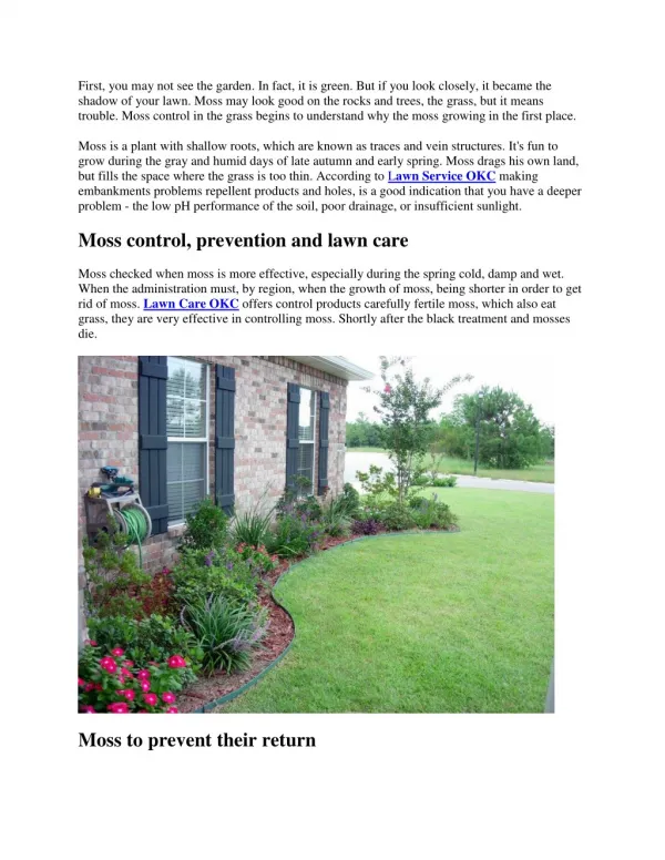
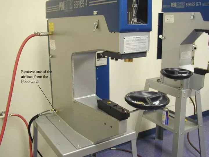
Remove one of the airlines from the Footswitch. …The Ram will fall by gravity. With the airline to the Footswitch disconnected…. Ram. Ram Jam Nut. Ram Jam Bushing. ..Turn clockwise with the top wrench until Ram Jam Nut loosens.

E N D
…The Ram will fall by gravity. With the airline to the Footswitch disconnected….
Ram Ram Jam Nut Ram Jam Bushing
..Turn clockwise with the top wrench until Ram Jam Nut loosens Place one wrench on the Ram Jam Nut and the other on the Ram Bushing…... Hold with the bottom wrench and...
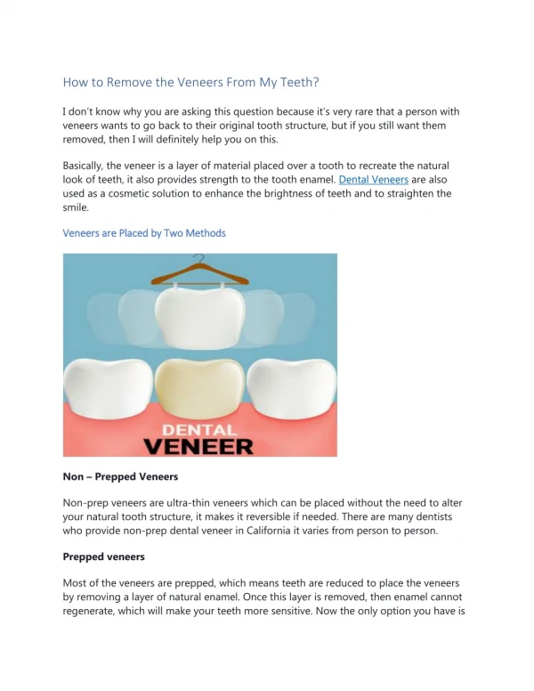
With Footswitch disconnected and Ram down, Install Punch (P/N 975200048) into the Ram Bushing and tighten set screws (2)
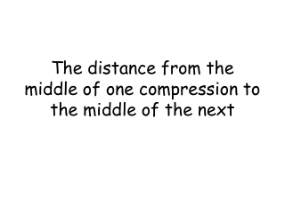
Select correct Anvil (See Tooling Guide in back of Manual), install into Anvil Holder and tighten set screw. Tooling Part Number
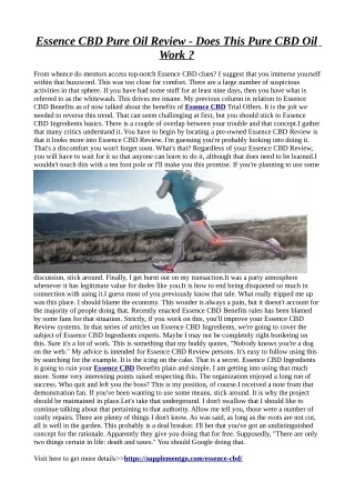
Turn Ram Force Adjustment to “Off” position Place the Set-Up/Cycle Switch to the “Set-Up” Position
Place hardware (Knurls up) on Anvil.( In the case of Studs, place panel over hole in the Anvil, then push stud through hole.)
With Force Adjustment set to off and Set-up/Switch in “Set-Up” Position, press Footswitch. Ram descends by gravity.
Rotate Punch clockwise until Punch makes contact with the surface of panel
Turn the Punch clockwise (2) additional turns. Tighten the Ram Jam Nut by turning it counter clockwise by hand The Safety is now set
Watch Lever With panel and hardware still in position and Footswitch depressed, slowly turn the Force Adjustment Knob clockwise... In “Set-Up” position
Release Footswitch. Panel and Hardware is held by Ram Force as long as Cycle/Set Up Switch in the “Set-Up” position.
Locate the Knurls on the hardware. Increase pressure until Knurls disappear into the Panel….
The Ram Force is Set.. The Safety is set... Before starting operation, disconnect one of the lines to the Footswitch and tighten the Ram Jam Nut with the 2 3/4 wrenches. Hold the Ram Brushing with one wrench and turn the Ram Jam Nut counterclockwise until snug. DO NOT OVERTIGHTEN. Press is now ready for operation.