Download
1 / 44
440 likes | 590 Vues
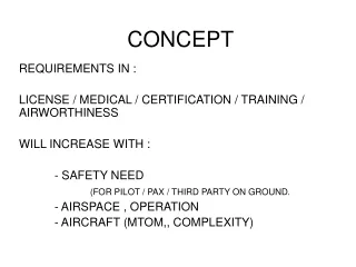
Networking Concept. CK NG Customer Service. Speaker 2006/XX/XX. Speaker 2007/XX/XX. WWW.Edge-Core.com. www.Edge-Core.com. What is Networking. Networking is the sharing of information and services Computer networks includes computers and computer operating systems

E N D
Networking Concept CK NG Customer Service Speaker 2006/XX/XX Speaker 2007/XX/XX WWW.Edge-Core.com www.Edge-Core.com
What is Networking • Networking is the sharing of information and services • Computer networks includes computers and computer operating systems • Computer networks are often classified by size, distance covered, or structure
Network Classification File Server+Print Server Printer ( Printer buffer) LAN LAN HD( Queued ) WAN Router Router • Local area network (LAN) • Small group of connected computers • <10Km • Mbps ~ Gbps • Ethernet (10Mbps), Fast Ethernet (100 Mbps), Gigabit Ethernet (1000Mbps) • Wide area network (WAN) • Interconnect LANs • Kbps ~ Mbps • Modem (33.6/56 kbps), X.25 (56 Kbps), Frame Relay (1.544 Mbps), T1 / E1 (1.544 Mbps), T3 / E3 (45 Mbps), ISDN 2B1D (64K),ATM (25 ~ 622 Mbps)
Required Network Elements • Three basic elements in Networking • Something to share--Network Services • A pathway of contacting others--Transmission media • Rules for communication--Protocol
Network Services • Network services are provided by numerous combinations of computer hardware and software • Service providers and requestors • Servers--Only provide services • Clients-- Only request services • Peers--Both
Network Services • File Services • File transfer, file storage and data migration, File update synchronization • Print services • Share printers, queue print jobs • Message services • E-mail, workgroup applications • Application services • Run software for network clients • Share processing power • Database services • Provide server-based database storage & retrieval function • Replication
Transmission Media (Protective Sheath) (Cladding) (Core) • A method or pathway for contacting each other • Cable media( twisted pair, coaxial, fiber optic cable) • Wireless media (radio frequency, microwave, infrared) RJ45 connector • Unshielded Twisted Pair Cable (UTP) Multi Mode 62.5/50 u core/ 125 u cladding Single Mode 8.3 u core/ 125 u cladding LC connector SC connector LC connector
Connectivity Devices • Network connectivity devices • Transmission media connectors • Network Interface Card • Modems • Repeaters • Hubs • Bridges • Switches • Internetwork connectivity devices • Routers • Brouters • CSU/DSUs
Protocol • Rules are required for communication between computer network devices • Specific communication rules and rule sets are called protocols
OSI Reference Model • 1977, ISO created the OSI Reference Model, Functional guideline for dividing up communication tasks OSI MODEL Application layer Provides services to the application. 7 Telnet , HTTP FTP , WWW …etc Presentation layer Converts, encrypts data. 6 JPEG , ASCⅡ EBCDIC , GIF…etc Network User Session layer Starts,stops session. Maintains order. 5 RPC , SQL NetBios names…etc Transport layer Ensures delivery of entire file or message. 4 TCP ,UDP ,SPX Network layer 3 Routes packets to LANs and WANs based on network address. IP ,IPX , Apple Talk DDP Data Link (MAC) layer Transmits frames from node to node based on station address. 2 802.3/802.2 , HDLC …etc Physical layer Passes information in bits across the connection medium. 1 EIA/TIA -232 , V.35 …etc
Physical Layer • Defines rules for transmitting bits of data • Structure of a network (physical topology) • Mechanical and electrical specifications for the transmission medium • Bit transmission encoding and timing rules • Bits
Data Link Layer • Organizes bits into logical groups called frames • Control information like source and destination addresses, frame length, and information about the upper layer protocols is added to the front end of the frame-header • Frame • MAC Sub-layer • Media access methods and logical topologies • Addressing • Data Link Sub-layer • Frame synchronization • Connection services • Connectionless • Non-reliable • Error control • Cyclic redundancy check (CRC)
Network Layer • Organizing messages into logical groups called datagram packets • Routing datagram packets to their correct destinations • Connectionless services • Connection-oriented services
Transport Layer • Provide end-to-end control and error-checking to determine if all the packets have arrived • Reliability
Session Layer • Connection services include connection establishment, maintenance, and tear-down • End-nodes exchange messages and agree to certain connection parameters, such as beginning sequence numbers and number of outstanding messages allowed • Dialog
Presentation Layer • Usually part of the OS and is responsible for formatting data • Encrypt and translate received packets • Format
Application Layer • Interface between user and computer • Provides network services to the user • Shared
OSI Reference Model Application Process Application Process Application Presentation Session Transport Network Data Link Physical Application Presentation Session Transport Network Data Link Physical A D P S T N DL
OSI Layer Mapping 802.1Q VLAN tagging Frame (64-1522 Bytes) 6 Bytes 6 Bytes 2 B 2 B 2 B 46-1500 Bytes 4 Bytes Layer 2 Destination Address Source Address 8100 TCI L/T Data Pad FCS 3 bits 1 bit 12 bits Priority CFI VLAN ID IP Packet Format 00 01 02 03 04 05 06 07 08 09 10 11 12 13 14 15 16 17 18 19 20 21 22 23 24 25 26 27 28 29 30 31 32 Version IHL Type of Service Total Length Identification Flags Fragment Offset Time to Live Protocol Header Checksum Source Address Layer 3 Layer 4 Destination Address Options Padding TCP Segment Format Data ... 00 01 02 03 04 05 06 07 08 09 10 11 12 13 14 15 16 17 18 19 20 21 22 23 24 25 26 27 28 29 30 31 32 Source Port Destination Port Sequence Number Acknowledge Number Data Offset Reserved U R G A C K P S H R S T S Y N F I N Window UDP Datagram Format 00 01 02 03 04 05 06 07 08 09 10 11 12 13 14 15 16 17 18 19 20 21 22 23 24 25 26 27 28 29 30 31 32 Source Port Destination Port Checksum Urgent Pointer Length Checksum Options Padding Data ... Data ... 7 Bytes 1 Byte 12 Bytes Layer 1 Preamble SFD Data IPG bits
LAN Standards • IEEE (Institute of Electrical and Electronics Engineers) • 1980, defining LAN standards for the Physical and Data Link layers of the OSI model • IEEE 802.2 LLC (Logical Link Control) • IEEE 802.3 CSMA/CD (Carrier Sense Multiple Access with Collision Detect) Ethernet • IEEE 802.4 Token Passing Bus • IEEE 802.5 Token Passing Ring • IEEE 802.6 MAN (Metropolis Area Network)
ISO/OSI vs IEEE802 ISO/OSI Model Application Presentation Session Transport Network Data Link Physical IEEE 802 standard IEEE 802 Upper Layer Protocol Logical link control Media access control Physical 802.2 logical link control MAC MAC MAC MAC 802.3802.4 802.5 802.6
Ethernet Technology Evolution Transceiver T-Connector Coaxial Cable Terminator Terminator 10Mbps AUI Cable Coaxial Cable Hub Cat 5 Cable 500M Star Topology 100M 185M Bus Topology Bus Topology IEEE 802.3 10BASE5 IEEE 802.3 10BASE2 IEEE802.3 10BASE-T 1970 1980 1983 1986 1991 1995 1999
IEEE 802.3 Ethernet 10BASE5 10BASE2 10BASE-T Thick Coaxial Cable Medium Thin Coaxial Cable Twisted pair Wire Bus Topology Star Bus CSMA/CD Access Method CSMA/CD CSMA/CD Max. Segment Length 185 M 500 M 100 M Transfer Rate 10 Mbps 10 Mbps 10 Mbps No. of Wire Pairs N/A N/A 2 Full Duplex? No No YES 3,4,5 Wiring Category N/A N/A
Carrier Sense Multiple Access/Collision Detection Frame 1 LISTEN Defferring Defferring Trannsmitting A B C .............. 2 SILENCE Defferring Carrier off Defferring Carrier off Idle A B C .............. 3 ACCESS Transmit Trial Transmit Trial Idle A B C .............. 4 BACK-OFF Backing offf Backing offf Idle A B C .............. 5 RETRY Successful Retry Backing offf Idle A B .............. C
Collision Domain 010101 1000011110101010101001010010 0101010 1101011 1110010110 0011110110 1110010110 0011110110 10 Mbps ( M = 10 ^ 6, bps = bit per second) BIT TIME = 0.1 ust = 1 ( bit ) / 10 M = 1 / 10 * 10^ 6 = 0.1 us Ethernet Packet Size = 64 ~ 1518 bytes (1 Bytes = 8 bits ) 64 Bytes = 64 * 8 bits = 512 bits Packet live = 512 / 10* 10 ^ 6 = 51.2 us /0.1 us = 512 delay bit-time Collision Domain = 51.2 us / 2 = 25.6 us 0101010 1101011 1110010110 0011110110 1110010110 0011110110
Collision 1000011110101010101001010010 101011 010101 1110010 0101010 1101011 1110010110 0011110110 1110010110 0011110110 110001111010101010100101001011100 1000011110 1000011110101010101001010010 101011 010101 1110010 0101010 1101011 1110010110 0011110110 1110010110 0011110110
IEEE 802.3u Fast Ethernet • Physical and logical topologies • Media independent interface(MII) • Auto Negotiation • Media access control (MAC)
Fast Ethernet Network Design 100BASE-FX 100BASE-T4 100BASE-TX Fiber optic cable Twisted pair Wire Medium Twisted pair Wire Star Star Star Topology CSMA/CD CSMA/CD CSMA/CD Access Method Max. Segment Length 100M 412 M 100 M 100 Mbps 100 Mbps 100 Mbps Transfer Rate 2 4 No. of Wire Pairs N/A Full Duplex? YES YES YES 5 3,4,5 Wiring Category N/A
Ethernet Speed Evolution Server Farms Gbps 10G Base 10GBase 100Mbps Switch Switch Cat 6 Cat 5e Cat 5 Cable 1000M 40KM Switch 100M 10GBase IEEE 802.3ab 1000BASE-TX IEEE 802.3z 1000Base-SX /1000Base-LX 100OBASE-CX IEEE 802.3u 100BASE-TX /100Base-FX /100Base-T4 1970 1980 1983 1986 1991 1995 1999
Gigabit Ethernet Standard Maximum Distance Cable 220M 550M Multimode fiber 1000Base-SX 850nm IEEE 802.3z Multimode fiber Single Mode Fiber 1000Base-LX 1300nm 220M 2000M IEEE 802.3z IEEE 802.3z 25M 1000Base-CX STP UTP Cat 5 (4 pair) 100M IEEE 802.3ab 1000Base-T
Need for Connectivity Devices • Overcome the limitations of the LAN media • Transport of data packets across multiple networks with different media access methods • Communication between systems with incompatible protocols
Network Device and OSI FTP Server WWW V IHL TOS Total Length Router Layer 3 Switch Metro Ethernet Switch Identification Flags Fragment Offset TTL Protocol Header Checksum Source Address Destination Address Options Padding 802.1Q VLAN tagging Source Port Data ... Destination Port Sequence Number Acknowledge Number Bridge Layer 2 Switch Data Offset Reserved U R G A C K P S H R S T S Y N F I N Window DA SA 8100 TCI L/T Data Pad FCS Checksum Urgent Pointer Options Padding Data ... Preamble SFD Data Repeater Layer 7 Layer 4 Layer 3 Layer 2 Layer 1 1980 1986 1995 2000 2005
Repeater/Hub Physical Physical Application Application Presentation Presentation Session Session Transport Transport Network Network Data Link Data Link Physical Physical Repeater Repeaters work at layer 1 of the OSI model Their primary function is to regenerate signal
Repeater/Hub • Physical Layer devices. • Protocol Independent. • Interconnect two or more network segments (with the same type) to be a larger network segment. • Regenerates the received digital signals. Does not process the received frames
Repeater/Hub (5-4-3 Rule) Reperter Reperter Reperter Reperter DTE 1 DTE 2 DTE 3 IRL IRL DTE 1 IRL = Inter Reperter Length
Hub (5-4 Rule) 10M Hub 10M Hub 100meter 100meter 10M Hub 10M Hub 100meter 100meter 100meter Station 100meter 100meter . . . Station
Shared Network Hub Hub Hub 10Base2 10Base5 10BaseT 100BaseT Collision Domain CSMA/CD Share 10Mbps or 100Mbps
Bridge/Switch Application Application Presentation Presentation Session Session Transport Transport Network Network Physical Physical Data Link Data Link Data Link Data Link Physical Physical Bridge Bridges work at layer 2 of the OSI model Their primary function is to relay frame
Bridge/Switch • MAC Layer devices • Protocol Independent • Interconnect two or more LANs • Process received frames based on the MAC addresses • Addressed Learning, Frames Filtering & Forwarding Function • Increase the total throughput of a LAN
Switched Network Segment • A • B • 1 2 3 • 4 5 6 1 2 3 4 5 6 Collision Domain 4 Collision Domain 3 A B 10Mbps X 4=40Mbps 100Mbps X 4=400Mbps Switch Collision Domain 1 Collision Domain 2
Router/Layer 3 Switch Application Application Presentation Presentation Session Session Transport Transport Network Network Network Physical Network Data Link Physical Data Link Data Link Data Link Physical Physical Router Router work at layer 3 of the OSI model Their primary function is to route packet
Router/Layer 3 Switch Router Broadcast Domain Broadcast Domain
Type of Hub/Switch • Dumb • Using it • Smart • Using it & knowing the situation • Make the decision • Intelligent • Using it, Knowing it & Controlling it
Comprehensive Network Management • Front Panel Management • Out-of-band management • Full set of network management • In-band SNMP management • Super set of network management • Web Management • Management from Everywhere • No learning Curve