Download

1 / 48
530 likes | 927 Vues
Top-down modular design. Decoders. n -to-2 n decoder: logic network with n inputs and 2 n outputs. One output is active for each of the 2 n input combinations each minterm Decoder minterm generator Most common use: Memory selection. Decoders.

E N D
Decoders • n-to-2n decoder: logic network with n inputs and 2n outputs. • One output is active for each of the 2n input combinations each minterm • Decoder minterm generator • Most common use: • Memory selection
Decoders • Parallel decoders (a) active-high (b) active-low
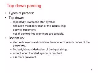
Decoders • Parallel is expensive • Problem extending for larger n • 2n decoders require n-input ANDs: fan-in • Alternative: (c) alternate structure
Decoders • Tree decoders – constant fan-in: 2-input gates throughout • Compare the number of gates required for (a) and (b) • Dual tree decoders • n inputs divided into 2 groups j and k; • n = j+k • j-input decoder 2j outputs • k-input decoder 2k outputs • Array of 2j * 2k = 2n 2-input ANDs
Decoders • Why decision tree: @a @a @a @a @a@a @a@a @a@a@a@a
Decoders: (c) dual tree • n=4 • j=k=2
Implementing logic functions using Decoders Since , each output can be considered a maxterm.
Logic functions using Decoders • Active-high decoder with OR gate (a) • Active-low decoder with NAND gate (b)
Logic functions using Decoders • Active-high decoder with NOR gate (c) • Active-low decoder with AND gate (d)
Decoders Active-high decoder with enable (a) Symbol (b) • Function:
Decoders • 3 8 decoder using two 2 4 decoders with enable
Decoders • 4 16 decoder using 2 4 decoders with enable
Encoders • Opposite of decoder: one output code (binary) for each input; assumes one input active at a time • n inputs; s outputs • n≤ 2s • s ≥ log2n; usually s = log2n • 4:2 encoder with exclusive inputs: functional diagram
Encoders • K-Maps of the 4:2 encoder outputs
Encoders • Logic diagram and Truth table of the 4:2 encoder
Encoders • Functional diagram and Truth table of the 4:3 encoder • Outputs Zero unless exactly one line is active high
Encoders • K-Maps of the outputs of the 4:3 encoder
Encoders • Logic diagram of the 4:3 encoder
Encoders • 4:2 priority encoder • No input active EO = 1 • At least one input active GS = 1 • If more than one input active output the one with highest priority • 3 > 2 > 1 > 0 • Useful in resourcemanagementrequest /acknowledgecircuits incomputers
Encoders • K-Maps of the 4:2 priority encoder outputs
Encoders • Logic diagram and Truth table of the 4:2 priority encoder
Multiplexers • Connects one of the inputs to the output • Needs log2n select lines
Multiplexers • Easy to realize in CMOS
Multiplexers • Question: we want a 8:1 MUX using 4:1s as building blocks
Demultiplexers • Connects the input to one of the outputs • Needs log2n select lines
Demultiplexers • Where is it useful?
Adders • Often realized as “bit slice”s • Bit slice: module that handles one bit position • Can be replicated (arrayed) • Array handles n bits (the whole number) • Bit slice: Half Adder • Given two input bits, produces sum and carry
Adders • Bit slice: Full Adder • Given two input bits and carry in, produces sum and carry
Adders • Pseudo parallel (ripple carry) Adder
Adders • Two-bit “parallel” Adder
Adders • Four-bit “parallel” Adder • What is the difficulty with n-bit parallel adders?
Adders • Parallel Adder carry logic: growing impractically • Generate Propagate
Adders • Expanding the carry expressions yields or, generalized:
Adders • When there is carry-in, it becomes c0, and renumbering the terms yields: • Can form groups of 4:
Adders • Using the group carries: • Generate and propagate are from one bit so far • Can extend the idea to groups of bit positions
Adders • The group carry, generate and propagate are: • The groups can be adjoining or overlappinge.g.
Adders • Subtraction is addition • Two-s complement • Bitwise invert B and set the carry-in c0=1
Adders • Overflow detection
Adders • Overflow detection
Comparators • Example: 2-bit comparator
Comparators • K-Maps of the comparator outputs
Comparators • Example: MIS 4-bit magnitude comparator
Comparators • 4-bit magnitude comparator function table
Comparators • Cascading 4-bit comparators to obtain a 16-bit comparator