Download
1 / 31
330 likes | 643 Vues
This chapter in the book includes: Objectives Study Guide 11.1 Introduction 11.2 Set-Reset Latch 11.3 Gated D Latch 11.4 Edge-Triggered D Flip-Flop 11.5 S-R Flip-Flop 11.6 J-K Flip-Flop 11.7 T Flip-Flop 11.8 Flip-Flops with Additional Inputs 11.9 Summary Problems

E N D
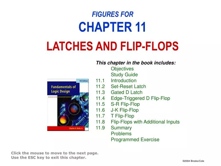
This chapter in the book includes: Objectives Study Guide 11.1 Introduction 11.2 Set-Reset Latch 11.3 Gated D Latch 11.4 Edge-Triggered D Flip-Flop 11.5 S-R Flip-Flop 11.6 J-K Flip-Flop 11.7 T Flip-Flop 11.8 Flip-Flops with Additional Inputs 11.9 Summary Problems Programmed Exercise FIGURES FORCHAPTER 11LATCHES AND FLIP-FLOPS Click the mouse to move to the next page. Use the ESC key to exit this chapter.
(c) truth table + Q = D Figure 11-13: D Flip-Flops
Figure 11-16: Setup and Hold Times for an Edge-Triggered D Flip-Flop
Operation summary: S = R = 0 no state change S = 1, R = 0 set Q to 1 (after active Ck edge) S = 0, R = 1 reset Q to 0 (after active Ck edge) S = R = 1 not allowed Figure 11-18: S-R Flip-Flop
(b) Figure 11-20ab: J-K Flip-Flop(Q Changes on the Rising Edge)
Figure 11-21: Master-Slave J-K Flip-Flop(Q Changes on Rising Edge)
(b) Q+ = T'Q+ TQ'= Q T Figure 11-22ab: T Flip-Flop
Figure 11-23: Timing Diagram for T Flip-Flop (Falling-Edge Trigger)
↑ ↑ Figure 11-25: D Flip-Flop with Clear and Preset ↓
Figure 11-26: Timing Diagram for D Flip-Flop with Asynchronous Clear and Preset