Download
1 / 62
620 likes | 761 Vues
Micro-CART Dec8-03 Micro processor – C ontrolled A erial R obotics T eam. Team Members. Team Leaders Jason Funk Karl Svec Client Lockheed Martin Advisor Dr. Greg Smith. Team Members Matt Beecher Andrew Crawford Mike Dent Phong Deo Anthony Nowell Dave Zajicek Yan Zhang

E N D
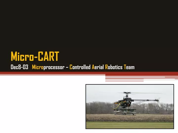
Micro-CARTDec8-03 Microprocessor – Controlled Aerial Robotics Team
Team Members • Team Leaders • Jason Funk • Karl Svec • Client • Lockheed Martin • Advisor • Dr. Greg Smith • Team Members • Matt Beecher • Andrew Crawford • Mike Dent • PhongDeo • Anthony Nowell • Dave Zajicek • Yan Zhang • Pilot • Nicholas Crego
Project History • Beginnings • Students wanted to develop a UAV to enter into a competition • Accomplishments: • Build Chassis • Tried different configurations of avionics boxes • Built low level software to read sensors • Manually flew and took readings
Project History • 3 years ago to 1 year ago • 2 students wrote nearly complete versions of avionics software, a ground station, and a simulator • Tested the avionics software in the simulator and it worked well • Installed avionics software on the system • Flight tests resulted in destroyed electronics • Determined to be caused by electronics not being electrically isolated from spark plug
Project History • 3 years ago to 1 year ago • Replaced nearly all of the electronics on the system • AeroEs rebuilt the helicopter and engine • Rewrote Ground Station in Java • Worked towards completing flight control software
Functional System Requirements • Autonomous flight • Visit 4 GPS waypoints • Over distance of 3km • Fly within 3 meters of waypoint • Avoid Fixed Obstacles • Fly over them at 50 ft • Hover at final waypoint • 2 way communication between Ground Station and Helicopter
Non-Functional System Requirements • Weight less than 14lb • Response time less than 1s
Work Breakdown Structure • Ground Station • Mike Dent • Dave Zajicek • Manual Override • Andrew Crawford • PhongDeo • Yan Zhang • Sensors • Anthony Nowell • Flight Control Software • Jason Funk • Filtering • Karl Svec • Matt Beecher
Overall Team Goal • Independent autonomous hover on Roll, Pitch, Yaw, Throttle, Collective Servo Channels • Complete, test, characterize, filter, and calibrate sensors (Sonar, GPS, Compass, Altimeter, IMU) • Complete manual override hardware • Fix trimming issues
Development Cycle Design Implement Bug Fix Lab Test Ground Test Analyze Analyze Flight Test
Ground Station • Purpose • Display current status of helicopter • Provide interface for setting navigation • Provide interface for setting control constants • Provide data logging / graphing capability • Initial Status • Receiving and displayingdata from helicopter • Intermittent problems sending data to the helicopter • Tasks • Fix outstanding communicationissues • Add manual trimming
Ground Station • Communication • Manual trimming of servos • Packet sending • Packet receiving • Information handling • Data logging • Manual / computer control indication • New real-time graphing capabilities
Ground Station 18 • Communication • Trim packets • Trim can be adjusted in real-time from the GS • Allows for tuning of servos before and during flight
Ground Station 19 • Communication • Packet sending - redundancy option • Send up to five identical Trim or PID packets • Compensates for possible packet loss/corruption
Ground Station 20 • Communication • Packet receiving - frequency option • Increase/decrease the rate at which helicopter sends state and dynamic PID packets • Allows for better resource management
Ground Station 21 • Information handling • Manual / computer control indication • Differentiate computer or manual control in logged data • New real-time graphing capabilities • Uses program called LiveGraph • Allows for quick and easy analysis of flight data
Ground Station • Final Status • New Communication, Graphing, & Trim features • Fully implemented and tested • Verified through ground and flight tests • Communication Testing Procedure • Initial communication loss: ~60% • Adjusted RF modem and serial port settings until best results received (~50% loss) • Implemented and tested state packet frequency functionality (now within satisfactory range ~5%)
2323 Flight Control Software • Purpose • Control helicopter movement • Initial Status • Sends calculated control data to servo controller based on the sensor data it receives. • Communication issues exist when receiving data from Ground Station • Tasks • Fix communication issues • Add dynamic trim control
2424 Flight Control Software • Task 1: Fix communication issues • Implemented dynamic communication frequencies • Task 2: Manual Trim Setting • Implemented dynamic trim setting
2525 Flight Control Software • Final Status • Communication to and from the ground station is far more reliable • Able to dynamically update trim • Able to dynamically update communications frequencies
Sensors 26 • Purpose • Provides the flight control software information about the helicopter’s position and orientation • Initial Status • IMU • Working • Altimeter • Microcontroller code was about half-written • Flight control code not started • Untested breadboard prototype
Sensors 27 • Initial Status • Compass • Code believed to be near complete • Not calibrated • Crashing flight control software • Sonar • Code believed to be near complete • Not calibrated • Not tested • GPS • No support for GPS module in flight control software
Sensors - Altimeter 28 • What was done • Software design • Initial flight control code • Began testing hardware
Sensors - Compass 29 • What was done • Resolved flight control instabilities • Calibrated in software (without engine noise)
Sensors - Sonar 34 • What was done • Calibrated in hardware • Bug fixing
GPS • Not able to fix onto satellites • Gets a fix when plugged into a laptop computer • Magnetic interference with compass
Sensors 38 • Final Status • Altimeter • Breadboard prototype nearly verified • Software is about half-implemented • Compass • Works in-lab • Suffers from magnetic interference from engine • Sonar • Reliable from 6 inches to about 18 feet (as opposed to the 20 foot specification) • GPS • Not reliable when used with helicopter SBC
Filtering • Purpose • Remove unwanted noise from sensor data • Initial Status • Some work had been done with RC, moving average, and Kalman filters • Performance was unsatisfactory, nothing actually implemented in code • Tasks • Select a practical filtering model • Design and implement filter code • Characterize sensor data • Calculate filter parameters
Filtering • Selecting a filtering model • Initially considered Kalman filter • Delivers very good performance and is the filter of choice for UAVs • Developing a process model for a helicopter is very difficult • Eventually decided on digital Butterworth filter • Well understood • Easy to implement in software • Computationally less expensive than alternatives (e.g. FIR filter)
Filtering • Filter Coefficients can vary with system changes • Store in XML file, parse at initialization • XML parser modified to read array of values • Tested by creating sample XML file, reading array of values and checking output with file
Filtering 46 • Final Status • ButterworthFilter class has been tested for correctness • IMU, Sonar, and Compass data have been characterized • Filters for the IMU, Sonar, and Compass are implemented in the flight control software
Manual Override 47 • Purpose • Switch between manual and computer control • Initial Status • Hardware designed, built, and tested for single servo channel • Later Flight Test results in relay chatter • Tasks • Build circuits for remaining servo channels
Initial Manual Override 48 • Design • Hardware used was RCATS relay for each servo channel • Tasks • Built for Pitch and Roll channels • Problems • Chatter causing undesired switch • Noise on PWM Control Signal
Revised Manual Override 50 • Design • ElectroDynamics manual override switch • Multiple NASA successful missions • Status • Hardware installed and tested for Roll and Pitch servo channels • Tasks • Implement for all servo channels independently