Download
1 / 15
170 likes | 450 Vues
Indium-Tin Oxide Sensors. Science Report. General. The primary goal of the ITO sensor project is to measure the concentration of Ozone (O 3 ) as a function of altitude. Ozone concentration will be measured with an Indium-Tin Oxide Sensor provided by Dr. Patel.

E N D
Indium-Tin Oxide Sensors Science Report
General The primary goal of the ITO sensor project is to measure the concentration of Ozone (O3) as a function of altitude. Ozone concentration will be measured with an Indium-Tin Oxide Sensor provided by Dr. Patel. These measurements will be compared to past measurements made by other payloads.
Data Format and Storage EEPROM will store all data collected on flight EEPROM stores addresses for flight software
Thermal Design • ITO Sensors must maintain temperatures between 24 and 30 degrees Celsius • Kapton Heater • Requires approximately 1W
Mechanical Design A hollow regular hexagonal prism FOAMULAR Insulating Sheathing External Design: The ITO sensor attached from the inner walls; minimal area of the ITO sensor is exposed Foam Divider in center of payload separates each board and power supply The external design of ITO sensor payload (in m)
FailureReport Results Issues/Solutions Future Work
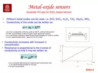
Results • EEPROM read-out showed all values as either 0 or 255 including the output of the thermistor control • ITO Sensor must be functional because it reacted to post-flight Tesla Coil output (may not be calibrated properly). • 4-Channel ADC must be functional because it is read properly and the proper I2COUT command is given to the EEPROM (this code worked in BR). • 8-Channel ADC is functional when not connected to conditioning board (connected to arbitrary 1.5V input and produced proper output. • Bad EEPROM?
Issues/Solutions • EEPROM not working • Blown during pre-flight work Monday • Solution: New EEPROM • Sensor calibrations are inaccurate • Resistance of sensor at just above 0 ppm is approximately 850Ω(not 970Ω). • Solution: Recalibrate sensors and modify conditioning board by using proper resistor values for actual ITO calibration in order to produce the proper amount of gain and offset
FutureWork • Once EEPROM and sensor issues are resolved, payload SHOULD be ready for flight. • System testing will determine whether or not the payload IS ready for flight. • Future flight requires that payload lose approximately 75g. • Payload box may be made with ½” foam instead of ¾” • ≈ 15 – 20g • Power supply for heater may be reduced • ≈ 30 – 45g • Reduce excess wire and ribbon cable • ≈ 15 - 20g