Download
1 / 33
330 likes | 511 Vues
ASEP -- Revision of D/F and OICA methods --. GRB informal meeting #13 6-7 November 2008 JASIC. Main Differences between D/F and OICA proposal. Anchor point. Pass < 0.0. Fail. 0.1 to 0.5. 0.6 <. The vehicles which fail D/F and pass OICA.

E N D
ASEP -- Revision of D/F and OICA methods -- GRB informal meeting #13 6-7 November 2008 JASIC
Main Differences between D/F and OICA proposal Anchor point
Pass < 0.0 Fail 0.1 to 0.5 0.6 < The vehicles which fail D/F and pass OICA Large difference between D/F and measured engine speed. These vehicles do not pass Annex3
How to define the engine speed for anchor point • Nurban=2.2PMR-0.43 (n-n_idle)/(s-n_idle) Power to mass ratio Difference (ΔN=Measured value - Nurban)
Pass < 0.0 Fail 0.1 to 0.5 0.6 < The vehicles which fail D/F and pass OICA
Same results of Mod. D/F and OICA vehicle 1-45 D/F Proposal OICA Proposal D/F:Fail OICA:Pass Mod. D/F: Pass Engine speeds are used Ni and Ni+1 for anchor point Gear:3rd, Annex3,i : 4th
Same results of Mod. D/F and OICA vehicle 200-14 D/F Proposal OICA Proposal D/F:Fail OICA:Pass Mod. D/F: Pass Engine speeds are used Ni and Ni+1 for anchor point Gear:2nd , Annex3,i : 4th
Pass < 0.0 Fail 0.1 to 0.5 0.6 < The vehicles which fail D/F and pass OICA Still different
Pass < 0.0 Fail 0.1 to 0.5 0.6 < The vehicles which fail D/F and pass OICA
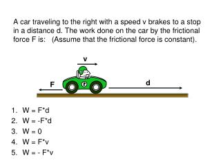
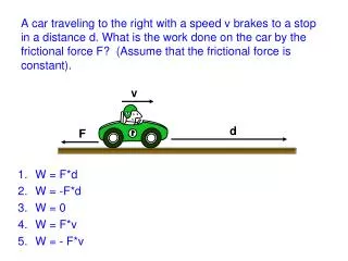
N1 diesel vehicle 3-01 OICA Proposal D/F Proposal D/F:Fail OICA:Pass Engine speeds are used Ni and Ni+1 for anchor point Mod. D/F: Fail Tolerance 2dB : Pass Sound Slope = 5.7dB/1000rpm N1 might be considered separately, because N1 vehicle’s design is different from passenger car’s. Gear:2nd , Annex3,i : 3rd
Pass < 0.0 Fail 0.1 to 0.5 0.6 < The vehicles which fail D/F and pass OICA Fail due to changing tolerance 3dB to 2dB
Influence of tolerance Vehicle 200-4 D/F Proposal OICA Proposal D/F:Fail OICA:Pass Mod. D/F: Fail Tolerance 2dB: Fail It seems that the tolerance 3dB may be necessary. Gear:2nd , Annex3,i : 5th
Influence of tolerance Vehicle 200-10 D/F Proposal OICA Proposal D/F:Fail OICA:Pass Mod. D/F: Fail Tolerance 2dB: Fail It seems that the tolerance 3dB may be necessary. Gear:3rd , Annex3,i : 4th
Distribution of sound slope Average 2nd : 5 dB/1000rpm 3rd : 6 dB/1000rpm D/F(UBA) uses fixed value, 5dB/1000rpm
Risk of the fixed sound slope The difference of sound slope 1dB/1000rpm causes the difference 3dB at the maximum engine speed. 5dB/1000rpm is average for 2nd gear. Therefore, a half of vehicles have larger slope. The sound slope in D/F should be modified or may use the individual slope. Vehicle: 200-6 Gear:2nd , Annex3,i : 4th 6.0dB/1000rpm (2nd)
Anchor point for OICA proposal Vehicle 100-22 OICA Proposal (Nwot,i; original) OICA Proposal (Nurban, i, i+1) The anchor points based on gear i, i+1, or 2 gears are in line with limit line Gear:2nd , Annex3,i : 4th PMR=124
Anchor point for OICA proposal Vehicle 200-10 OICA Proposal (Nwot,i; original) OICA Proposal (Nurban, i, i+1) The anchor points based on gear i, i+1, or 2 gears are in line with limit line Gear:2nd , Annex3,i : 4th , PMR=181
Summary (1) • The result of D/F proposal with modified engine speed for anchor point is same as that of OICA method with 2dB tolerance. (But the tolerance should be optimized.) • The sound slope in D/F should be modified or may use the individual slope. • N1 might be considered separately, because N1 vehicle’s design is different from passenger car’s. However, D-range tests on automatic transmission have the other problem.
Consideration for modifyiing the OICA proposal on D-range test for CVT Vehicle 1-10 OICA proposal compensate tyre nosie only at the anchor point. There is the influence of tyre noise at every point as well as at the anchor point, bcause the relationship between vehicle speed and engine speed is not liner in case of CVT. D/F proposal cannot create a limit line. Gear:D-range , Annex3,i : D-range
6000 6000 5000 5000 4000 4000 D-range Engine speed(Nbb), rpm Engine speed(Nbb), rpm 3000 3000 D-range Annex3(D) Annex3(D) Nmax 2000 2000 Nmax 1000 1000 Vehicle 1-12 Vehicle 1-10 0 0 20 30 40 50 60 70 80 90 100 20 30 40 50 60 70 80 90 100 Vehicle speed(Vbb), km/h Vehicle speed(Vbb), km/h 6000 6000 5000 5000 4000 4000 Engine speed(Nbb), rpm Engine speed(Nbb), rpm 3000 3000 D-range Annex3(D) 2000 2000 Nmax ASEP(D) Annex3(D) Vehicle 1-16 1000 1000 Vehicle 1-14 Nmax 0 0 20 30 40 50 60 70 80 90 100 20 30 40 50 60 70 80 90 100 Vehicle speed(Vbb), km/h Vehicle speed(Vbb), km/h Non linear relationship
dB B A rpm Modified OICA proposal for D-range test Vehicle 1-10 A B Same engine speed but different vehicle speed 0.7 dB Influence of tyre noise Should use maximum vehcle speed within ASEP test for the calculation of the anchor point
Modified OICA proposal for D-range test Vehicle:ASEP 1-10 (original) Vehicle:ASEP 1-10 (mod.) Vehicle:ASEP 1-12 (original) Vehicle:ASEP 1-12 (Mod.)
Modified OICA proposal for D-range test Vehicle:ASEP 1-14 (original) Vehicle:ASEP 1-14 (Mod.) Vehicle:ASEP 1-16 (original) Vehicle:ASEP 1-16 (Mod.)
Comparison between the D/F and OICA proposal on D-range test for CVT D/F D-range test OICA D-range test Step-1 : Measure_Annex3 : Lurban, Lcrs Step-2 : Measure ASEP_data : N@Lmax, Lmax Step-3 : Calculate Anchor Point Step-4 : Calculate Limit Curve L_ASEP(n,v) Step-1 : Same Step-2 : Measure ASEP_data : N@BB, Lmax Step-3 : Calculate Anchor Point Step-4 : Calculate Limit line L_ASEP(slope) Repeat Step2 to Step 4 for the number of ASEP data A lot of calculation steps
Consideration for low noise vehicles Near Annex3 limit Vehicle 99-4 Low noise Vehicle 1-47 Lurban=71.5dB Lurban=69.0dB 72-69=3dB margine The reference lines of D/F and OICA are same Should add a margine of Annex3 limit Vehicle 99-8 Vehicle 1-45 Lurban=69.2dB Lurban=69.2dB Lurban=72.4dB 72-69.2 =2.8dB margine
Summary (2) To revise the OICA proposal; • Should be revised compensation of anchor point in case of D-range test for the automatic transmission. • Should be considered a margin of Annex3 to apply to ASEP for low noise vehicles.
398 rpm (7.7 %) Vehicle 1-12 Vehicle 1-10 492 rpm (10.0 %) 511 rpm (9.8 %) 512 rpm (11.7 %) 201 rpm (3.3) % Vehicle 1-14 534 rpm (11.0 %) Vehicle 1-16 225 rpm (4.4 %) 538 rpm (11.1 %) Narrow range of engine speed for CVT Is it necessary to test ASEP for such vehicles?
How about lower engine speed of Annex3? There is no example that exceeds the noise level of Annex3 below the engine speed of Annex3.
Engine speed during Annex3 (2) Lower engine speed are already covered in Annex 3
Summary (3) • May skip ASEP test when Annex3 covers the engine speed in ASEP. • Not necessary to test below Annex3 (anchor point)