Download
1 / 25
250 likes | 453 Vues
Automation Totalflow Measurement & Control Systems Example Applications. One Wide Area Network, Six Local Area Networks and 19,250 Remote Sites on MAS Radio Systems. ME. WASHINGTON. MINNESOTA. N. DAKOTA. VT. MONTANA. MICHIGAN. NH. OREGON. NY. MA. WISCONSIN. S. DAKOTA. CT. RI.

E N D
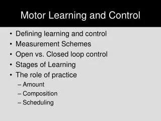
Automation Totalflow Measurement & Control Systems Example Applications
One Wide Area Network, Six Local Area Networksand 19,250 Remote Sites on MAS Radio Systems ME WASHINGTON MINNESOTA N. DAKOTA VT MONTANA MICHIGAN NH OREGON NY MA WISCONSIN S. DAKOTA CT RI IDAHO MICHIGAN WYOMING PA IOWA NJ NEBRASKA OHIO MD INDIANA appox 1000 mi / 1600 km DE ILLINOIS NEVADA WV VIRGINIA MISSOURI COLORADO KANSAS KENTUCKY UTAH BartlesvilleOffice CALIFORNIA N. CAROLINA Farmington100 Wells Perryton5000 Wells NEW MEXICO OKLAHOMA TENNESSE S. CAROLINA ARKANSAS ARIZONA Hobbs 600 mi/950 km T1 microwve MISSISSIPPI 2000 Wells Odessa LOUISIANA GEORGIA ALABAMA LafayetteOffice TEXAS 12,000 Wells HoustonOffice FLORIDA Offshore150 Wells
Miles 0 200 400 Atlantic Ocean Pacific Ocean Gulf of Mexico ABB - TOTALFLOW Large System Example Conoco - Large system distributed throughout USA. - Field offices connected via telemetry to home office (Houston, TX). -Real-time access to/from all remote devices.
Conductor NT or Other SCADA Package WinCCU, TDS, VAS/AMS Gas ABB Prod/Test Separator ABB ABB Condensate ABB ABB Water ABB ABB ABB ABB - TOTALFLOW Typical Conoco Production Site Application: Wellhead Casing/Tubing Pressure Monitoring (transmitters) Wellhead SSV Control (solenoid) Separator Condensate and Water Volumes (turbine meters) Gas flow rates and volumes (6400 or 6700) Tank level and temperature (LevelMaster) Gas Delivery Valve control(flow rate, nomination, DP, AP, etc.)
ABB - TOTALFLOW Conoco Host System Topology
ABB - TOTALFLOW Conoco System Features/Functions Locations Lobo Laredo Zapata Hebronville 1400 Units 64/67/6600 FCU New Mexico Farmington 400 Units 64/67/6600 FCU Mertzon Mertzon, Tx 300 Units 64/67/6600 FCU W. Virginia Charleston 200 Units 6713 FCU System features: Valve Control, Compressor Monitoring, Radio Communication, Plunger Lift, System Diagnostics, Real-time Data Access, Trending, Exception Reporting, Allocation Royalty Accounting/Reporting, DDE/OPC link to host SCADA, SSD
Integrated Production Facility with Gas, Liquid and Tank Level Measurement
E/P Multi-tube Meter Station with Tube Switch Control and Station Flowrate Control with 6713 plus ExIO and 4-20 ma current loops FR1 6410 DO 1,2 4-20ma DI 7,8 DO 7,8 FR2 6410 DO 3,4 Station Flowrate Control Valve FR1+FR2 6713 (w/PI-RTU) Primary Tube FlowRate = FR1 + Fr2 + FRprimary
E/P Multi-tube Meter Station with Tube Switch Control and Station Flowrate Control with 6713 BaseBoard and Modbus data link FR1 6410 DO 1,2 RS484,Modbus DO 7,8 DI 7,8 FR2 6410 DO 1,2 Station Flowrate Control Valve FR1+FR2 6713 (base board… no ExIO) Primary Tube FlowRate = FR1 + Fr2 + FRprimary
Flow Rate and Pressure Controlat Pipeline Delivery Points Production Wells
SOME RTU DATA Water Tanks Level Inj Vol Curr Day’s Total Inj Vol Prev Day’s Total Inj Vol Totalizer Inj Pump On/Off Status Inj Pump Alarm Status Inj. Pump Curr Discharge Press Inj Pump Prev Day’s Press Avg Inj Pump Curr Day’s Press Avg (Pressure Avgs reflect pump on time only) Water Injection SystemRTU Doing Water Volume Measurement and Status/Statistics on Compressor PI AIs DI PT Water Tanks Water Turbine Meter PT ESL Water Inj. Pump Pump On/Off
Level Alarms with VAS Spill Sensor ALARM IF 1. Spill Sensed OR 2. Last Enabled Oil Tank Full Host Site DIKE Oil Tks Water Tanks Remote Site
SA-RTU / Tank Gauge Schematic Radio Port LapTop Port SA-RTU AuxPort RS485 …... Tank Gauge #10 Tank Gauge #1 Tank Gauge #2
Pump-Off Control • Maximizes ProductionWhile Minimizing Cost • Saves Lost ProductionDue to Frequent Workovers • Reduces Wear on Rod String, Pump and Gear Box • Fewer Pump Strokes Per Day • Protects Against Rod Parts Damage • Caused by Fluid Pound • Saves Energy Costs by Not Operating Partly Filled Pump • Protects From Gas Locking • Increases the Economic Life of Stripper Wells • Available as application using • Stand Alone Unit, as 6400 or 6700 Series Flow Computers or 6790 RTU-PLC
Plunger Lift Plug-In RTU Performs: Plunger Lift Application and Valve Control Flow Computer Monitoring: Differential Pressure Line Pressure Computing Flow Rate Tubing Transmitter Control Valve Plunger Arrival Sensor • Increases gas production by keeping liquids off the formation • Generally speaking, used on wells that do not have enough constant downhole pressure to free flow into a gathering system • General Scheme • Steel Plunger is inserted into the production tubing • Shut-in causes plunger to fall allowing fluid to collect above plunger • Different methods used to decide how long to shut-in and flow well • Downhole pressure is used to life the plunger and fluid to surface • Adaptive algorithms make adjustments in order to optimize plunger rise time.
Valve Controller Options • Digital controller • Uses two digital outputs to control direction of valve • Uses two digital inputs to detect full open and closed position • Only consumes current when moving valve • Analog controller • Uses one analog output to open and close valve • Uses two digital inputs to detect full open and closed position • Interfaces to standard I/P converters
Differential Pressure Static Pressure Flow Rate Differential Pressure Overrides (High & Low) On/Off Timer and/or Pressure Operation Pressure Override Nominations Valve Control Modes
Intermitter Controller Features Optional Timer Mode: On Time = Hours:Minutes Off Time = Hours:Minutes 6713 Flow Computer Optional Pressure Transmitter 100% 100% Restart Set-Point DP Low Limit 0% 0% Valve will shut-in after delay time Valve will open (Start control, Nominations etc.)
Pressure Override Feature • Programmable pressure override limit • Override can cause valve to fail close • Programmable pressure restart value if valve is closed • Typical Application: Automatic Well shut-in ifcompressor goes down. Auto restart well when compressor is repaired 6713 Flow Computer Pressure Transmitter Control Valve Compressor
Nomination Features • Flow Nomination Target Volume • Selectable Start and Stop Date • Monitors and Adjusts Valve Automatically to Insure Correct Volume Deliveries • Works in Conjunction with other On/Off Control
Proportional Sampling on Flow Computer • Two Digital Outputs available to provide a signal to sampler(s) • User enters a volume set point in MCF • Output energizes for 5 seconds then resets (Standard 12 VDC, Optional contact closure)
Kansas Deliverability Test (KDT) • Automatically conduct periodic Kansas State Deliverability Test on either a single or a Group of Wells. • Record data entered manually and/or automatically • Report Data From Test
Pressure Buildup Test • Used in conjunction with Valve Control • Automatic Well Shut-in • User specified time period for test • Record increases in pressure after shut-in • Used by reservoir engineers