Download
1 / 15

E N D
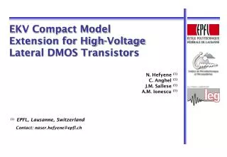
M. Pedro1, J. Galán1, T. Sánchez-Rodríguez1, R. Jiménez1, C. Luján-Martínez2 and R. G. Carvajal2 1 Dpto. de Ingeniería Electrónica, de Sistemas Informáticos y Automática,University of Huelva, Spain 2 Dpto. de Ingeniería Electrónica, Escuela Superior de Ingenieros de Sevilla, University of Sevilla, Spaintrinidad.sanchez@gie.esi.us.es A Compact Voltage-Controlled Transconductor with High Linearity
Outline Introduction Topologies based on FVFCS Proposed Transconductor Transconductor Simulation Results Transconductor Experimental Results Conclusions
1. Introduction • The operational transconductance amplifier has become the choice for high frequency signal processing. • Modern wireless communication systems demand the design of high linear transconductors. • An additional required property is the tuning capability in a wide range maintaining the linearity and the input range. • The use of modern technologies and the reduction of power supply voltages are making difficult the design of transconductors with high linearity and reasonable dynamic range. • Different transconductor circuit techniques that rely on transistors operating in the triode region have been proposed. Proposed Transconductor Transconductor Simulation Results Transconductor Experimental Results Topologies based on FVFCS Introduction Conclusions
2. Topologies Based on FVFCS • Very low impedance at node X • The voltage at node X is set by the current source Ibiasand the voltage Vcp. • The node X can sink large current variations at the input but the quiescent voltage at this node is essentially constant. • The gate of M2 translate the large current variations into compressed voltage variations at the drain of M3. • This voltage is used to generate scaled replicas of the input current by means of transistor M4. FVFCS Proposed Transconductor Transconductor Simulation Results Transconductor Experimental Results Topologies based on FVFCS Introduction Conclusions
2. Topologies Based on FVFCS • This cell has been also used as class-AB output stage or as a current mirror where transistor M2 is biased near the triode region and M4 is in saturation region. • In this case, the output current can increase several times compared to the input current. • This mode of operation is not suitable for very low-voltage environment. FVFCS Proposed Transconductor Transconductor Simulation Results Transconductor Experimental Results Topologies based on FVFCS Introduction Conclusions
2. Topologies Based on FVFCS • M1 operating in saturation region • M2 operating in saturation region (class AB) or near triode region (super class-AB) • This kind of topology achieves a current boosting proportional to Iin2 and therefore to Vi4 outperforming classical class-AB transconductor topologies. • If M1 were working in triode region, a linear voltage to current conversion will be achieved. The main drawback is the low input dynamic range. Class-AB o Super Class-AB operation Proposed Transconductor Transconductor Simulation Results Transconductor Experimental Results Topologies based on FVFCS Introduction Conclusions
3. Proposed Transconductor • M1 operating in triode region and M2 operating in saturation region • If VSD1 is kept constant, Iin is perfectly linear with VGS1. • The scheme formed by transistors M2, M3 and Ibias forces a constant voltage at drain of M1. • The voltage Vcp can be used as control voltage to tune the input current Iin. Proposed linear operation Proposed Transconductor Transconductor Simulation Results Transconductor Experimental Results Topologies based on FVFCS Introduction Conclusions
3. Proposed Transconductor • In pseudo-differential transconductors, the linearity and the transconductance depend on the common-mode input voltage. • Due to the dependence of the signal common-mode output voltage over the tuning mechanism, a CMFF circuit must be included. • A current proportional to the common-mode input signal ViCM and the control signal Vprog is generated and subtracted at the output nodes. Proposed Transconductor Transconductor Simulation Results Transconductor Experimental Results Topologies based on FVFCS Introduction Conclusions
3. Proposed Transconductor • The main contribution of distortion is the mismatch between transistors M2 and M4 in the FVFCS scheme and the dependence of the transconductance with the programmability. Proposed Transconductor Transconductor Simulation Results Transconductor Experimental Results Topologies based on FVFCS Introduction Conclusions
4. Transconductor Simulation Results Designparametersforthe Transconductor Proposed Transconductor Transconductor Simulation Results Transconductor Experimental Results Topologies based on FVFCS Introduction Conclusions
4. Transconductor Simulation Results • Gm from 5 to 53 µA/V Proposed Transconductor Transconductor Simulation Results Transconductor Experimental Results Topologies based on FVFCS Introduction Conclusions
5. Transconductor Experimental Results Proposed Transconductor Transconductor Simulation Results Transconductor Experimental Results Topologies based on FVFCS Introduction Conclusions
5. Transconductor Experimental Results -72 dB -62 dB Proposed Transconductor Transconductor Simulation Results Transconductor Experimental Results Topologies based on FVFCS Introduction Conclusions
6. Conclusions • A linear tunable transconductor based on a FVFCS scheme has been presented. • The programmability technique is based on the parallel of a transistor operating in triode region with others operating in saturation. • Experimental results show a good performance of the transconductor regarding to linearity. A total harmonic distortion of -72 dB is achieved. • The proposed transconductor is quite suitable for the design of continuous-time filters. Proposed Transconductor Transconductor Simulation Results Transconductor Experimental Results Topologies based on FVFCS Introduction Conclusions