Download
1 / 179
1.89k likes | 2.31k Vues
ECE 271 Electronic Circuits I. Topic 3 Diodes and Diodes Circuits. Chap 3 - 1. Chapter Goals. Develop electrostatics of the pn junction Define regions of operation of the diode (forward bias, reverse bias, and reverse breakdown)

E N D
ECE 271 Electronic Circuits I Topic 3Diodes and Diodes Circuits Chap 3 -1 NJIT ECE-271 Dr. S. Levkov
Chapter Goals • Develop electrostatics of the pn junction • Define regions of operation of the diode (forward bias, reverse bias, and reverse breakdown) • Explore various diode models including the mathematical model, the ideal diode model, and the constant voltage drop model • Apply the various types of models in circuit analysis • Explore diode applications • Explore different special types of diodes • Understand the SPICE representation and model parameters for the diode. Practice simulating diode circuits using SPICE Chap 3 -2 NJIT ECE-271 Dr. S. Levkov
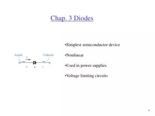
Diode Introduction • A diode is formed by joining an n-type semiconductor with a p-type semiconductor. • A pnjunction is the interface between n and p regions. • Study of diodes will consist of three sections: 1. PN-junction physics 2. Diode circuits analysis 3. Diode applications Diode symbol Chap 3 -3 NJIT ECE-271 Dr. S. Levkov
1. The pn junction A simple (or doped) semiconductor does not in itself possess properties that make it useful for electronic circuits. Chap 3 -4 NJIT ECE-271 Dr. S. Levkov
1. The pn junction A simple (or doped) semiconductor does not in itself possess properties that make it useful for electronic circuits. However, when a section of p-type material and a section of n-type material are brought in contact to form a pn junction, a number of interesting properties arise. Chap 3 -5 NJIT ECE-271 Dr. S. Levkov
1. The pn junction A simple (or doped) semiconductor does not in itself possess properties that make it useful for electronic circuits. However, when a section of p-type material and a section of n-type material are brought in contact to form a pn junction, a number of interesting properties arise. The major effect happens in the small section around the contact area – depletion region, where the holes and electrons recombine leaving no charge carriers. Chap 3 -6 NJIT ECE-271 Dr. S. Levkov
1. The pn junction A simple (or doped) semiconductor does not in itself possess properties that make it useful for electronic circuits. However, when a section of p-type material and a section of n-type material are brought in contact to form a pn junction, a number of interesting properties arise. The major effect happens in the small section around the contact area – depletion region, where the holes and electrons recombine leaving no charge carriers. Chap 3 -7 NJIT ECE-271 Dr. S. Levkov
pn Junction Electrostatics Donor and acceptor concentration on either side of the junction. Concentration gradients give rise to diffusion current - ID Chap 3 -8 NJIT ECE-271 Dr. S. Levkov
Space-Charge (Depletion) Region at the pn Junction • If the diffusion process was to continue unabated, this would result eventually in the uniform concentration of e. & h. through the entire semiconductor and pn junction would disappear. • This does not happen because the competing process appears that oppose the diffusion current. • As holes diffuse from p-region they leave (-) ionized atoms of acceptors. As electrons diffuse from n-region they leave (+)ionized atoms of donors • This creates the space-charge or depletion region with localized (-) and (+) charge electric field E(x) drift current that oppose the diffusion current. NJIT ECE-271 Dr. S. Levkov Chap 3 -9
Drift Currents • Gauss’ Law: an electric field due to the charge distribution is • Assuming constant permittivity* and one dimension • Resulting electric field gives rise to a drift current IS of minority carriers. With no external circuit connections, drift and diffusion currents cancel: IS= ID . (There is no actual current, since this would imply power dissipation, rather the electric field cancels the diffusion current ‘tendency.’) • The equilibrium condition is maintained by the barrier voltage V0,or , in another words, junction potential . *In electromagnetism, permittivity is the measure of how much resistance is encountered when forming an electric field in a medium NJIT ECE-271 Dr. S. Levkov Chap 3 -10
Potential Across the Junction Electric Field Charge Density Potential Using (charge neutrality), it can be shown that NJIT ECE-271 Dr. S. Levkov Chap 3 -11
Width of Depletion Region From the previous expressions, the expression for the width of the space-charge region, or depletion region can be obtained. It is called the depletion region since the excess holes and electrons are depleted from the dopant atoms on either side of the junction. NJIT ECE-271 Dr. S. Levkov Chap 3 -12
Example 1. Width of Depletion Region Problem: Find built-in potential and depletion-region width for given diode Given data:On p-type side: NA = 1017/cm3 on n-type side: ND = 1020/cm3 Assumptions: Room-temperature operation with VT = 0.025 V Analysis: with NJIT ECE-271 Dr. S. Levkov Chap 3 -13
Example 2. Diode Electric Field and p,n depletion width • Problem: Find the size of the individual depletion layers on either side of a pn junction and the max. value of the electric field for a given diode. • Given data: On the p-type side: NA = 1017/cm3 on the n-type side: ND = 1020/cm3 from earlier example, • Assumptions: Room-temperature operation • From charge neutrality we have , • and , and . • Thus Hence NJIT ECE-271 Dr. S. Levkov Chap 3 - 14
Example 2. Diode Electric Field and p,n depletion width (cont.) For the electric field, we have that from and the diagram on slide 3.8 it follows that is equal to the area under triangle. Since is the base of the triangle, it follows NJIT ECE-271 Dr. S. Levkov Chap 3 - 15
The equilibrium in pn junction - summary Result of diffusion created by the difference of concentration of holes and electrons in different parts of pn junction: holes will diffuse from left to the right and electrons from right to the left. This process results in diffusion current that creates the difference of potential at the depletion region. This is the majority carrier diffusion current. NJIT ECE-271 Dr. S. Levkov Chap 3 -16
The equilibrium in pn junction - summary Result of diffusion created by the difference of concentration of holes and electrons in different parts of pn junction: holes will diffuse from left to the right and electrons from right to the left. This process results in diffusion current that creates the difference of potential at the depletion region. This is the majority carrier diffusion current. However, this difference of potential acts like a battery making an electric field that creates drift current. This is the minority carrier current also known as reverse saturation current NJIT ECE-271 Dr. S. Levkov Chap 3 -17
The equilibrium in pn junction - summary Result of diffusion created by the difference of concentration of holes and electrons in different parts of pn junction: holes will diffuse from left to the right and electrons from right to the left. This process results in diffusion current that creates the difference of potential at the depletion region. This is the majority carrier diffusion current. However, this difference of potential acts like a battery making an electric field that creates drift current. This is the minority carrier current also known as reverse saturation current Under equilibrium conditions, the diffusion current is exactly balanced by the drift current so that the net current across the p–n junction is zero, NJIT ECE-271 Dr. S. Levkov Chap 3 -18
The equilibrium in pn junction - summary Result of diffusion created by the difference of concentration of holes and electrons in different parts of pn junction: holes will diffuse from left to the right and electrons from right to the left. This process results in diffusion current that creates the difference of potential at the depletion region. This is the majority carrier diffusion current. However, this difference of potential acts like a battery making an electric field that creates drift current. This is the minority carrier current also known as reverse saturation current Under equilibrium conditions, the diffusion current is exactly balanced by the drift current so that the net current across the p–n junction is zero, When no external current or voltage is applied to the p–n junction, the potential gradient (barrier voltage ) forms an energy barrier that prevents further diffusion of charge carriers across the junction. NJIT ECE-271 Dr. S. Levkov Chap 3 -19
The pn junction under the applied voltage condition When an external battery is connected across a pn junction, the amount of current flow is determined by the polarity of the applied voltage and its effect on the space–charge region. When the battery polarity is applied in the same direction as barrier voltage we say that a pn junction is in reverse bias. When the battery polarity is applied in the opposite direction to barrier voltage we say that a pn junction is in forward bias. NJIT ECE-271 Dr. S. Levkov Chap 3 -20
The pn junction in reverse bias + +++ --- - The free electrons in the n–type material are attracted toward the positive terminal of the battery and away from the junction NJIT ECE-271 Dr. S. Levkov Chap 3 -21
The pn junction in reverse bias + +++ --- - - The free electrons in the n–type material are attracted toward the positive terminal of the battery and away from the junction, creating new holes NJIT ECE-271 Dr. S. Levkov Chap 3 -22
The pn junction in reverse bias + +++ --- - The free electrons in the n–type material are attracted toward the positive terminal of the battery and away from the junction, creating new holes and the positive charge on the right of depletion region becomes even more positive. NJIT ECE-271 Dr. S. Levkov Chap 3 -23
The pn junction in reverse bias + + +++ --- - The free electrons in the n–type material are attracted toward the positive terminal of the battery and away from the junction, creating new holes and the positive charge on the right of depletion region becomes even more positive. The holes from the p–type material are attracted toward the negative terminal of the battery and away from the junction, NJIT ECE-271 Dr. S. Levkov Chap 3 -24
The pn junction in reverse bias + + +++ --- - + The free electrons in the n–type material are attracted toward the positive terminal of the battery and away from the junction, creating new holes and the positive charge on the right of depletion region becomes even more positive. The holes from the p–type material are attracted toward the negative terminal of the battery and away from the junction, creative negatively charged ions NJIT ECE-271 Dr. S. Levkov Chap 3 -25
The pn junction in reverse bias + + +++ --- - The free electrons in the n–type material are attracted toward the positive terminal of the battery and away from the junction, creating new holes and the positive charge on the right of depletion region becomes even more positive. The holes from the p–type material are attracted toward the negative terminal of the battery and away from the junction, creative negatively charged ions, and the negative charge on the left of depletion region becomes more negative. NJIT ECE-271 Dr. S. Levkov Chap 3 -26
The pn junction in reverse bias + + +++ --- - The free electrons in the n–type material are attracted toward the positive terminal of the battery and away from the junction, creating new holes and the positive charge on the right of depletion region becomes even more positive. The holes from the p–type material are attracted toward the negative terminal of the battery and away from the junction, creative negatively charged ions, and the negative charge on the left of depletion region becomes more negative. As a result, the space–charge region at the junction becomes effectively wider, and the potential gradient increases until it approaches the potential of the external battery. NJIT ECE-271 Dr. S. Levkov Chap 3 -27
The pn junction in reverse bias + + +++ --- - The free electrons in the n–type material are attracted toward the positive terminal of the battery and away from the junction, creating new holes and the positive charge on the right of depletion region becomes even more positive. The holes from the p–type material are attracted toward the negative terminal of the battery and away from the junction, creative negatively charged ions, and the negative charge on the left of depletion region becomes more negative. As a result, the space–charge region at the junction becomes effectively wider, and the potential gradient increases until it approaches the potential of the external battery. Current flow is then extremely small because no voltage difference ( electric field ) exists across either the p–type or the n–type region. NJIT ECE-271 Dr. S. Levkov Chap 3 -28
The pn junction in forward bias - The free electrons in the p–type material near the positive terminal of the battery break their electron–pair bonds and enter the battery, NJIT ECE-271 Dr. S. Levkov Chap 3 -29
The pn junction in forward bias - - The free electrons in the p–type material near the positive terminal of the battery break their electron–pair bonds and enter the battery, creating new holes, NJIT ECE-271 Dr. S. Levkov Chap 3 -30
The pn junction in forward bias - The free electrons in the p–type material near the positive terminal of the battery break their electron–pair bonds and enter the battery, creating new holes, which reduce the negative space charge on the left . NJIT ECE-271 Dr. S. Levkov Chap 3 -31
The pn junction in forward bias - The free electrons in the p–type material near the positive terminal of the battery break their electron–pair bonds and enter the battery, creating new holes, which reduce the negative space charge on the left . The electrons from the negative terminal of the battery enter the n–type material NJIT ECE-271 Dr. S. Levkov Chap 3 -32
The pn junction in forward bias - - The free electrons in the p–type material near the positive terminal of the battery break their electron–pair bonds and enter the battery, creating new holes, which reduce the negative space charge on the left . The electrons from the negative terminal of the battery enter the n–type material, diffuse toward the junction NJIT ECE-271 Dr. S. Levkov Chap 3 -33
The pn junction in forward bias - The free electrons in the p–type material near the positive terminal of the battery break their electron–pair bonds and enter the battery, creating new holes, which reduce the negative space charge on the left . The electrons from the negative terminal of the battery enter the n–type material, diffuse toward the junction, and reduce the positive space charge on the right. NJIT ECE-271 Dr. S. Levkov Chap 3 -34
The pn junction in forward bias The free electrons in the p–type material near the positive terminal of the battery break their electron–pair bonds and enter the battery, creating new holes, which reduce the negative space charge on the left . The electrons from the negative terminal of the battery enter the n–type material, diffuse toward the junction,and reduce the positive space charge on the right. As a result, the space charge region becomes effectively narrower, and the energy barrier decreases to an insignificant value. NJIT ECE-271 Dr. S. Levkov Chap 3 -35
The pn junction in forward bias - The free electrons in the p–type material near the positive terminal of the battery break their electron–pair bonds and enter the battery, creating new holes, which reduce the negative space charge on the left . The electrons from the negative terminal of the battery enter the n–type material, diffuse toward the junction,and reduce the positive space charge on the right. As a result, the space charge region becomes effectively narrower, and the energy barrier decreases to an insignificant value. Excess electrons from the n–type material can then penetrate the space charge region, flow across the junction, and move by way of the holes in the p–type material toward the positive terminal of the battery, creating large diffusion current This electron flow continues as long as the external voltage is applied, with resulting diode current. NJIT ECE-271 Dr. S. Levkov Chap 3 -36
The pn junction in diode summary - reverse saturation current of minority carriers NJIT ECE-271 Dr. S. Levkov Chap 3 -37
Diode Junction Potential for Different Applied Voltages NJIT ECE-271 Dr. S. Levkov Chap 3 -38
Diode i-v Characteristics NJIT ECE-271 Dr. S. Levkov Chap 3 -39
Diode i-v Characteristics NJIT ECE-271 Dr. S. Levkov Chap 3 -40
Diode i-v Characteristics NJIT ECE-271 Dr. S. Levkov Chap 3 -41
Diode i-v Characteristics Figure 3.9 Pspice model here NJIT ECE-271 Dr. S. Levkov Chap 3 -42
Diode Equation where IS = reverse saturation current (A) vD = voltage applied to diode (V)q = electronic charge (1.60 x 10⁻¹⁹ C)k = Boltzmann’s constant (1.38 x 10⁻²³ J/K)T = absolute temperaturen = nonideality factor (dimensionless)VT = kT/q = thermal voltage (V) (25 mV at room temp.) ISis typically between 10-18 and 10-9 A, and is strongly temperature dependent due to its dependence on ni2. The nonideality factor is typically close to 1, but approaches 2 for devices with high current densities. It is assumed to be 1 in this text. NJIT ECE-271 Dr. S. Levkov Chap 3 -43
Diode Voltage and Current Calculations (Example) Problem: Find diode voltage for diode at room-temperature dc operation for different specifications with VT = 0.025 V. If IS = 0.1 fA, ID = 300 mA NJIT ECE-271 Dr. S. Levkov Chap 3 -44
Diode Voltage and Current Calculations (Example) Problem: Find diode voltage for diode at room-temperature dc operation for different specifications with VT = 0.025 V. If IS = 0.1 fA, ID = 300 mA If IS = 10 fA, ID = 300 mA NJIT ECE-271 Dr. S. Levkov Chap 3 -45
Diode Voltage and Current Calculations (Example) Problem: Find diode voltage for diode at room-temperature dc operation for different specifications with VT = 0.025 V. If IS = 0.1 fA, ID = 300 mA If IS = 10 fA, ID = 300 mA With IS = 0.1 fA, ID = 1 mA, NJIT ECE-271 Dr. S. Levkov Chap 3 -46
Diode Current for Reverse, Zero, and Forward Bias • Reverse bias: for example: NJIT ECE-271 Dr. S. Levkov Chap 3 -47
Diode Current for Reverse, Zero, and Forward Bias • Reverse bias: for example: • Zero bias: NJIT ECE-271 Dr. S. Levkov Chap 3 -48
Diode Current for Reverse, Zero, and Forward Bias • Reverse bias: for example: • Zero bias: • Forward bias: NJIT ECE-271 Dr. S. Levkov Chap 3 -49
Semi-log Plot of Forward Diode Current and Current for Three Different Values of IS Only small 60mV increase in the forward voltage is needed to raise the diode current by 10. NJIT ECE-271 Dr. S. Levkov Chap 3 -50