Download
1 / 23
360 likes | 1.38k Vues
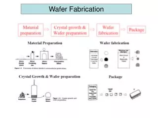
NOVEL WAFER BONDING TECHNOLOGY SURVEY. Po-Wen Chen Department of Electrical Engineering and Graduate Institute of Electronics Engineering National Taiwan University, Taipei, Taiwan, R.O.C. Outline. Introduction Wafer bonding Wafer bonding application TEM inspection of our

E N D
NOVEL WAFER BONDING TECHNOLOGY SURVEY Po-Wen Chen Department of Electrical Engineering and Graduate Institute of Electronics Engineering National Taiwan University, Taipei, Taiwan, R.O.C.
Outline Introduction Wafer bonding Wafer bonding application TEM inspection of our bonding achievement
Clean(hydrophilic) Alignment Pre-bonding Anneal Introduction
Wafer Bonding Anodic Bonding Silicon Direct Bonding/Fusion Bonding Intermediate-Layer Bonding
Anodic Bonding • Rely on charge migration • Silicon and glass with alkali metal • Glass with 3.5% Na2O • Negative voltage to glass to • attract and neutralize Na+ • Due to electric field , O2- • transported to glass-silicon • interface form SiO2 • Electrostatic attraction between • glass-silicon interface
Anodic Bonding • Enhance positive ion mobility at • 500℃ • Produce uniform bonds,but charged • carriers make it incompatible with • active device • Useful for pressure sensors, solar • cells and piezoresistive and package • applications
Silicon Direct Bonding/Fusion Bonding • Join silicon wafer by • Create and contact hydrophobic or hydrophilic surfaces • Anneal at high temperature • Hydrophobic case • HF dip before contact • More challenging than hydrophilic wafer ,but ultimately better? • Hydrophilic case • SC1(standard cleaning) before bonding
AfterSC1 ,the mirror polished silicon wafer filled with hydroxyl radicals(OH- ) OH- on polished silicon face permit a good initial contact bond Silicon Direct Bonding/Fusion Bonding
Subsequent heating dehydrates OH- cause oxidation of the bonding surface resulting in a Si-O-Si bond As annealing temperature are increased beyond 1000℃ ,the strength of the bond approaches that of silicon itself Viscosity and pressure of ambient gas ,wafer contact energy influence speed Silicon Direct Bonding/Fusion Bonding
Silicon Direct Bonding/Fusion Bonding • Press in the middle of wafer to create a preliminary point of contact • While mechanical spacer maintain wafer physically separated • Retract spacer to form a single bonding wave from center to wafer • Spacer integrity is important • Multiple bonding waves promote warpage and voids • Gas trapped in pocket form by multiple waves
From room temperature 110C Slow fracture effect and interface water rearrangement From 110 C to 150 C Polymerization of silanol groups across the interface From 150 C to 800 C Bonding energy limited by contacted area From 800 C and above Complete bonding via oxide flow Silicon Direct Bonding/Fusion Bonding
Influence of particle Schematic of particle leading to an unbonded area Ex :a particle of about 1um diameter leads to an unbonded area with a diameter of about 0.5cm of typical 4-in diameter silicon wafers with a thickness of 525um
Influence of surface R>2tw R<2tw
Intermediate-Layer Bonding Options for intermediate layer bonds
Intermediate-Layer Bonding Eutectic and glass-frit bonding techniques • Deposition of intermediate metallic and glass films • Eutectic bond • Examine a two component phase diagram • Little solubility between the component , reveal eutectic point located at the lowest melting temperature • Alloy • Formed by solid-liquid inter-diffusion at contact interface • Followed by solidification upon cooling • Gold and silicon • 363℃,2.85%Si,97.1%Au by weight • Good eutectic bond • Remove silicon oxide films that hamper gold diffuse into silicon
Intermediate-Layer Bonding • Before bonding • Exposure to ultraviolet light to remove organic contaminants • Low temperature • Reach eutectic point make this technique attractive for active device processes • Glass frit bond • Create hermetic seals using relatively low temperature • Thin glass layer is deposited and pre-glazed • Wafer brought into contact at rated melting temperature of glass ,less than 600℃ • Pressure is applied to maintain contact • Lead borate with significant lead oxide content is often used
Checking for wafer-to-wafer bonding integrity • Three dominant methods for imaging a bonded pair of silicon wafer • Infrared transmission • Ultrasonic • X-ray topography
Visualization of the bonded wafer pair X-ray topography Ultrasonic IR transmission
Wafer bonding application BESOI (ELTRAN) Smart-cut