Download
1 / 22
230 likes | 368 Vues
On the Performance Properties of the Minkowski Island Fractal Antennas Ahmed M. Abdul-Lettif 1 , M. A. Z. Habeeb 2 , and H. S. Jaafar 3 1 College of Science, Babylon University Hilla, Iraq, Email: abdullettif@yahoo.com 2 Ministry of Science and Technology, Baghdad, Iraq

E N D
On the Performance Properties of the Minkowski Island Fractal Antennas Ahmed M. Abdul-Lettif1, M. A. Z. Habeeb2, and H. S. Jaafar3 1College of Science, Babylon University Hilla, Iraq, Email: abdullettif@yahoo.com 2Ministry of Science and Technology, Baghdad, Iraq 3College of Science, Karbala University, Karbala, Iraq
Abstract- The performance properties of the square loop antenna (MO), Minkowski island of one iteration (M1), and Minkowski island of two iterations (M2) have been investigated using NEC4 which is moment-method- based software. The numerical simulations show that Minkowski island fractals can be used to achieve miniaturization in antenna systems while keeping an identical electromagnetic performance. It is demonstrated that M1 and M2 antennas exhibit multiband and broadband behavior, and as the number of iterations of the Minkowski fractal increases, the resonant frequencies increase and the bandwidth of each single band increases. Also, it is found that increasing the number of iterations of the fractal antenna causes a decrease in the antenna gain, input impedance, and voltage standing wave ratio, and it enhances the antenna matching. Index Terms- Fractal antennas, Minkowski island, multiband antennas, small antennas.
I. INTRODUCTION With the widespread proliferation of telecommunication technology in recent years, the need for small-size multiband antennas has increased manifold. However, an arbitrary reduction in the antenna size would result in a large reactance and deterioration in the radiation efficiency. As a solution to minimizing the antenna size while keeping high radiation efficiency, fractal antennas can be implemented. A fractal is a rough or fragmented geometric shape that can be subdivided in parts, each of which is (at least approximately) a reduced-size copy of the whole [1-4]. Fractal are space filling contours, meaning electrically large features can be efficiently packed into small areas [5,6]. Since the electrical lengths play such an important role in antenna design, this efficient packing can be used as a viable miniaturization technique. Miniaturization of a loop antenna using fractals was shown by Cohen [7,8]. A first attempt to explore the multifrequency properties of fractals as radiating structures was done by Puente and Pous [9].
In many cases, the use of fractal antennas can simplify circuit design, reduce construction costs, and improve reliability. Because fractal antennas are self-loading, no antenna tuning coils or capacitors are necessary. Often they do not require any matching components to achieve multiband or broadband performance. Fractal antennas can take on various shapes and forms. Among those currently reported in the literature include koch fractal [10], the Sierpinski gasket [11, 12], Hilbert curve [13], and the Minkowski island fractals [14]. Some of these geometries have recently been pursued for antenna applications because of their inherent multiband nature. However, incorporation of fractal geometries into the antenna structures, and various aspects of their optimization, are still in the incipient stages. The majority of this paper will be focused upon the Minkowski island fractal antennas.
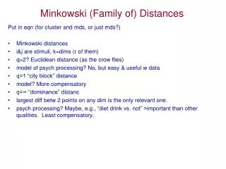
II. MINKOWSKI ISLAND FRACTAL GEOMETRY In order for an antenna to work equally well at all frequencies, it must satisfy two criteria: it must be symmetrical about a point, and it must be self-similar, having the same basic appearance at every scale: that is, it has to be fractal. The shape of the fractal is formed by an iterative mathematical process. This process can be described by an iterative function system (IFS) algorithm, which is based upon a series of affine transformations [15]. An affine transformation in the plane can be written as: where x1 and x2 are the coordinates of point x. If r1=r2=r with 0<r<1, and 1=2=, the IFS transformation is a contractive similarity (angles are preserved) where r is the scale factor and is the rotation angle. The column matrix t is just a translation on the plane.
Applying several of these transformations in a recursive way, the Minkowski island fractals are obtained as depicted in Fig.1. The intiator is a square which can be regarded as a zeroth order of the Minkowski island fractal (MO). Each side of the square is modeled with 10 segments each of them has a length of 6 cm and a diameter of 2mm. The Minkowski island fractal of one iteration (M1) is formed by displacing the middle third of each side by some fraction of 1/3. By applying the same procedure on M1, the Minkowski island fractal of second iteration (M2) is obtained. It should be pointed out that the area of M1 is 37.4% smaller than that of MO, and the area of M2 is 54.5% smaller than that of MO.
(a) (b) (c) Fig. 1. Geometry of Minkowski island fractal of (a) zeroth order (MO), (b) one iteration (M1), and (c) two iterations (M2).
III. NUMERICAL SIMULATIONS Numerical simulations were done using NEC4 WIN95 VM, which is a moment-method-based software. The moment method implies an approximation of integral equations in terms of unknown currents I(l) of the body [16,17]. The body may either be a length of perfectly conducting wire or a perfectly conducting surface. The integral equation for the unknown current I(l) induced on the wires follows directly from enforcing the boundary condition, which implies that, the tangential component of the electric field vector to vanish on the surface of perfectly conducting wires. The moment method incorporates periodic boundary conditions. This allows for only one element of the periodic array to be simulated. When studying intricate elements such as fractals, this saves time and allows wide frequency sweeps that for some cases would not otherwise fit into the limitations of the computing hardware. Dielectrics were not incorporated, although some of the practical implementations do require dielectric support.
Since all details of the radiation pattern follow from knowledge of the electric and magnetic dipole moments of the charge and current distribution in the antenna, these factors should be analyzed. For MO antenna, the feed source is placed at the middle of the upper side. The current distribution resembled a sinusiod pattern. Through the program simulations, it was shown that the current is able to flow through the fractal wire almost as if it were flowing through a straight wire of the same effective length. The current distribution is given by where I1 and I2 are the currents on the lower and upper sides of the square loop, and k is the wave vector. where I3 and I4 are the currents on the left and right sides.
Since the vector potential (A) of the loop is in general given by [16] and since the electric field vector (E) is given by then by using the expression [16]
one can obtain Equation (9) gives the electric far field.
Radiation patterns were generated at the resonant frequencies of the antenna. The resonant frequencies could be predicted from the plot of standing wave ratio (SWR) versus the frequency as shown in Fig.2. It can be noted from this figure that MO antenna has one resonant frequency at 135 MHz, M1 antenna has three resonant frequencies at 135, 248, and 480 MHz, and M2 antenna has four resonant frequencies at 135, 245, 335, and 455 MHz. It is interesting to note that Minkowski fractal antennas are not only broadband, but they also demonstrate multiband effects. This is due to the coupling between the wires. As more contours and iterations of the fractal are added, the coupling becomes more complicated and different segments of the wire resonate at different frequencies. It is worth mentioning that as the number of iterations of the fractal increases, the antenna has more resonant frequencies due to the self similarity in the geometry, and the bandwidth of each single band increases. The values of SWR for a 50 transmission line at f=135 MHz for MO, M1, and M2 antennas are 2.62, 1.34, and 1.02 respectively. The radiation patterns at the resonant frequency of 135 MHz for MO, M1, and M2 antennas are shown in Fig.3. The corresponding three dimentional plots of the radiation patterns are depicted in Fig.4.
5 (a) (b) 4 SWR 3 2 (c) Fig. 2. SWR versus the frequency for (a) MO antenna, (b) M1 antenna, and (c) M2 antenna. 230 180 380 280 130 330 430 480 f (MHz) 5 4 SWR 3 2 330 480 380 280 430 130 180 230 f (MHz)
(a) (b) (c) Fig. 3. Radiation pattern at the resonant frequency of 135MHz for (a) MO antenna, (b) M1 antenna, and (c) M2 antenna.
(b) (a) (c) Fig. 4. 3-D radiation pattern at the resonant frequency of 135MHz for (a) MO antenna, (b) M1 antenna, and (c) M2 antenna. Z axis Y axis
It is interesting to note that the radiation patterns of MO, M1, and M2 antennas are almost the same. This indicates that these antennas exhibit virtually identical electromagnetic radiation behavior, independent of the defferences in antenna size and geometry. What is also worth mentioning is the similarity between the other band’s patterns of each M1 amd M2 antenna. This is the proof for a truly multiband performance of the antenna. The input impedance of a small linear diopole of length () and wire radias (a) can be approximated by [18]
Or it can be measured, as it is done in this work, by a rotation on the Smith chart to adjust the model of antenna to an RLC circuit. The Smith charts for MO, M1, and M2 antennas centered at the frequency of 135 MHz are depicted in Fig. 5. This figure shows that the matching of M2 antenna is better than the matching of M1 antenna, and this in turn is better than the matching of MO antenna. The input impedances of MO, M1, and M2 antennas at the frequency of 135 MHz are 124.83-j25.05, 66.83-j2.14, and 49-j0.5 respectively. Other aspects of the Minkowski fractal antenna performance properties to consider are the gain and the half power beamwidth (HPBW). The gains of MO, M1, and M2 antennas relative to an isotropic source, which radiats equally in all directions, were computed to be 2.98, 2.62, and 2.32 dBi respectively. The HPBW was found to be 88 for MO antenna and 90 for each of M1 and M2 antenna. A summary of the performance properties of the investigated antennas at the resonant frequency of 135 MHz is presented in Table 1.
TABLE 1 PERFORMANCE CHARACTERISTICS OF THE MINKOWSKI ISLAND ANTENNAS AT THE RESONAT FREQUENCY
(a) (b) (c) Fig. 5. Smith chart of (a) MO antenna, (b) M1 antenna, and (c) M2 antenna centered at 135MHz.
REFERENCES [1] B. B. Mandelbrot, The Fractal Geometry of Nature, San Francisco, CA: Freeman, 1983. [2] M. F. Barnsley, R. L. Devaney, B. B. Mandelbrot, H. O. Peitgen, D. Saupe, R. F. Voss, Y. Fisher, and M. Mc Guire, The Science of Fractal Images, New York; Springer-Verlag, 1988. [3] H. O. Peitgen, H. Jurgens, and D. Saupe, Chaos and Fractals, New York: Springer-Verlag, 1990. [4] H. Jones, D. E. Reeve, and D. Saupe, Fractals and Chaos, A. J. Crilly, R. A. Earnshaw, and H. Jones, Eds. New York: Springer-Verlag, 1990. [5] K. Falconer, Fractal Geometry: Mathematical Foundations and Applications, New York, Johen Wiley & Sons, 1990. [6] H. Lauwerier, Fractals: Endlessly Repeated Geometrical Figures, Princeton, New Jersey: Princeton University Press, 1991. [7] N. Cohen, “Fractal Antennas Part 1: Introduction and the Fractal Quad.” Communications Quarterly Summer, 1995: 7-22. [8] N. Cohen, “Fractal Antennas Part 2: A Discussion of Relevant, but Disparate Qualities” Communications Quarterly Summer, 1996: pp. 53-66.
[9] C. Puente and R. Pous, “Fractal design of multiband and low side-lobe arrays”, IEEE Trans. Antennas Propagat. Vol. 44, pp. 1-10, May 1996. [10] C. Puente, J. Romeu, R. Pous, J. Ramis, and A. Hijazo, “Small but long Koch fractal monopole”, Electron. Lett. vol. 34, pp. 9-10, 1998. [11] C. Puente, J. Romeu, R. Pous, and A. Cardama, “On the behavior of the Sierpinski multiband fractal antenna”, IEEE Trans. Antennas Propagat. vol. 46, no. 4, pp. 517-524, Apr. 1998. [12] D. H. Werner, R. L. Haupt, and P. L. Werner, “Fractal antenna engineering: the theory and design of fractal antenna arrays”, IEEE Antennas Propagat. Mag. vol. 41, pp. 37-59, 1999. [13] K. J. Vinoy, K. A. Jose, V. K. Varadan, and V. V. Varadan, “Hilbert curve fractal antenna: A small resonant antenna for VHF/UHF applications, Microwave and Optical Technology Letters, vol. 29, no. 4, pp. 215-219, May 2001. [14] J. P. Gianvittorio and Y. Rahmat-Sami, “ Fractal antennas: A noval miniaturization technique and applications”, IEEE Antennas Propagat. Mag. vol. 44, no.1, pp. 20-36, 2002. [15] D. H. Werner and S. Ganguly, “ An overview of fractal antenna engineering research”, IEEE Antennas Propagat. Mag. vol. 45, no.1, pp. 36-56, 2003.
[16] W. I. Stutzman and G. A. Thiele, Antenna theory and design, John Wiley & Sons, New York, 1998. [17] A. S. Barlevy and Y. Rahmat-Sami, “Charactrization of electromagnetic band-gaps composed of multiple periodic tripods with interconnecting vias concept, analysis and design”, IEEE Trans. Antennas Propagat. vol. 49, no. 3, Mar. 2001. [18] C. A. Balanis, Antenna theory: analysis and design, 2nd Ed., New York, John Wiley & Sons, 1997.