Download
1 / 38
380 likes | 514 Vues
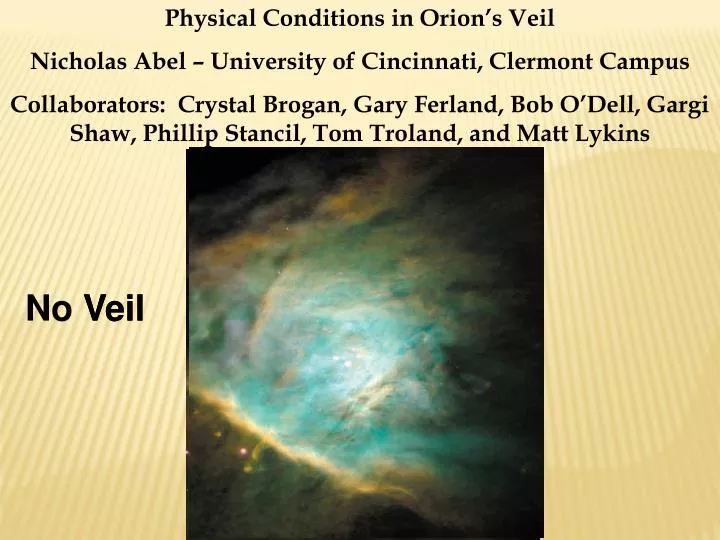
Physical Conditions in Orion’s Veil Nicholas Abel – University of Cincinnati, Clermont Campus Collaborators: Crystal Brogan, Gary Ferland, Bob O’Dell, Gargi Shaw, Phillip Stancil, Tom Troland, and Matt Lykins. Veil. No Veil. Outline. Background Observational Properties

E N D
Physical Conditions in Orion’s Veil Nicholas Abel – University of Cincinnati, Clermont Campus Collaborators: Crystal Brogan, Gary Ferland, Bob O’Dell, Gargi Shaw, Phillip Stancil, Tom Troland, and Matt Lykins Veil No Veil
Outline Background Observational Properties Why is Veil important? What we want to know? Data Analysis – Results
HST image of Orion Nebula (O’Dell & Wong 1996) Sketch of Orion Nebula made by Christiaan Huygens (1659). Taken from The Orion Nebula (O’Dell – 2004)
$27.95 on Amazon…Buy Now!!!! € 22.81 on Amazon…Buy Now!!!! 95.62 PLN na Amazon ... KupTeraz!!
Extinction Map, From of 20 cm and Hβ Emission τ 4861~ CHβ/0.434 High extinction here, hence “Dark Bay” Towards Trapezium, AV ~ 1.6 mag Veil is at least as large as the H II region. O’Dell and Yusef-Zadeh (2000)
Lyα Absorption with STIS (Cartledge et al. 2001) Towards Trapezium N(HI) = (4.8 ± 1.1)x1021 cm-2 About 60% of that seen in the ISM RISM ~3.1. Grains in Veil are larger than typical, not as efficient in extinguishing UV and Optical
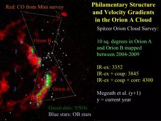
Magnetic Field Map of Veil (Troland et al. 1989) • Magnetic Field map, from Zeeman 21cm splitting. • Magnetic field strength • Blos ~50μG towards Trapezium • Also have 21 cm optical depth profiles throughout the Veil.
21 cm Optical Depth Profile Towards Trapezium Component B Component A Proportional to N(H)/Tspin N(H)/Tspin[A] = 1.78x1019 cm-2 K-1 N(H)/Tspin[B] = 2.35x1019 cm-2 K-1 Abel et al. (2004, 2006)
Abel et al. (2004, 2006) S III
The Veil is also seen in UV and optical absorption studies, using the Trapezium as a continuum source. • Veil has two main neutral components towards the Trapezium, both redshifted. • Has an ionized component, which is redshifted. • Both components seen in radio, UV, and optical ( I will focus on radio, UV). • Linewidth of each component in UV puts constraints on kinetic temperature and turbulent motions. H2 VLA B A Component A Component B STIS Spectra
b-values for Hydrogen puts constraints on kinetic temperature and turbulent motions. • Component A = 1.2 km/s (+/- 0.02). • Component B = 2.3 km/s (+/- 0.02). • STIS data also, for the first time, observed H2 in absorption. H2 VLA B A Component A Component B STIS Spectra
Why is Veil important? • Distance of neutral components (is/was?) one of the major uncertainties in the geometry of the Orion environment. • Wealth of observational data on gas and dust provides excellent test for calculations of physical conditions in the ISM. • H2 formation and destruction processes fundamentally important in study of PDRs, molecular clouds, star-formation. • Star formation controlled by balance of thermal, magnetic, gravitational, and turbulent energies. Veil offers the chance to compare each in a region associated with a nearby region of active star-formation.
What do we want to know about the Veil? • Wealth of data allows us to investigate physical characteristics. This includes. • Energy and pressure balance in the Veil • Thermal, Turbulent, and Magnetic • Relationship of kinetic and spin temperatures • Geometry • Distance of Veil from Trapezium • Thickness of each component • Dynamical evolution • Molecular hydrogen in the Veil • Abundance. • Why so low? • In order to do this, we need to determine the density, temperature, and column density in each component. • Combination of theoretical calculations and observational analysis
H I Column Density in Each Component • Observations of Kr I Absorption in UV (this works for O I, Cu II, and C I too). • Kr should all be Kr0 for neutral layers • Kr not depleted, assume Kr0/H0 ratio is constant • We know all but N(H0) in components A and B, so we can solve for it.
Can determine N(H) in each component
Column Density in Each Component • Final result is: • From 21 cm optical depth, we immediately get the spin temperature (ranges include error, ( ) is value from central H I column density)
Calculations • A series of theoretical calculations were performed using the spectral synthesis code Cloudy (Ferland et al. 1998). • CI, CI*, and CI** constrain density and temperature. • Observations of ions in multiple ionization stages, such as S, Mg, and C constrain distance to Trapezium. • Unfortunately, we do not have such data for each component, only average over both components from IUE data. Can only get average distance of both components. • Upper limit on H2 constrains ratio of UV field to density. • Linewidths constrain temperature for each component. Cloudy and Friends, 1999
Calculations • Well known set of elemental abundances for Orion • Assuming Veil abundances mimic Orion. • Well known grain properties • Large R model from Weingartner & Draine (2001), whose application in Cloudy is described in van Hoof et al. (2004). • Well known stellar continuum • O6V star θ1 Ori C, with some contributions from the other Trapezium stars. • Know when to stop the model, at N(H0) column density of each component.
Calculations • Perform a series of calculations which varies density of Veil and distance of Veil from Trapezium. • Problem, we do not see more than one ionization state of an element in multiple components • We do see averages (over both components) of several elements ionization stages seen in IUE data (Shuping & Snow 1997). • Mg0/Mg+ ~ 10-3.4 • C0/C+ ~10-3.7 • S0/S+ ~ 10-3.0 • We also know that distance cannot be so far away that no H2 forms. • Distance cannot be so close that we see the Veil glow in emission, so models have to predict less Hβ than coming from M42.
Log[N(H2)] Must be < 17.35 Taken from Abel et al. (2004)
Log[IHβ] Must be significantly less than -11.3, the value observed in M42.
H2 and Hβ Constraint: Combination of density/distance dramatically reduced. Taken from Abel et al. (2004)
CI**/Citot very sensitive to density over this region of parameter space.
Tkinetic Tkinetic very sensitive to density over this region of parameter space.
A B
Tkinetic A B
Distance and Density • Given all constraints from observations, best fit model to all data gives the average distance of neutral components (not each component) as: • 1018.8(+/- 0.1) (about two parsecs) • CI*, CI** data, combined with observational constraints on the model, give the density of each component as: • nH = 102.5 (component A) • nH = 103.4 (component B)
Results • From density, we get temperature in each component. • Tkin = 50 K (component A) • Tkin= 80 K(component B) • As a result, for both components in the Veil, Tkin < Tspin (H I level populations are not in thermal equilibrium). • Since we know the density and column density for each component, we can calculate average thickness, which is: • LA = 1.3pc • LB = 0.5pc
Energetics • Now that we have density, temperature, and magnetic field in each component, can compare energetics. • Using the formalism in Heiles & Troland (2005), we computed the ratio of thermal to magnetic energy density βtherm, and turbulent to magnetic energy density βturb. • In the ISM, βtherm < 1 and βturb ~ 1 • βturb ~ 1 means equipartition between magnetic and turbulent energies, while βtherm < 1 means magnetic energy dominates of thermal in the ISM
Energetics • For component A • Very narrow linewidth, combined with Tkin ~50, means less velocity for turbulent motions. • Smaller density in component A than component B. • βturb =0.01 in component A, making Veil unique as a region dominated by magnetic energy. • Component B, βturb =0.5, so in rough equipartition.
Molecular Hydrogen Absorption Calculations • Our calculations predicted that most H2 in Veil would be in states with J >1. • H2 level populations in Veil pumped by UV radiation, not controlled by collisions. • Veil is on verge of forming large amounts of H2, just barely not thick enough.
Summary • Neutral Veil layers are about 2 parsecs from Trapezium. • UV field about 2000 greater than ISRF (G0 = 2000). • In addition, ionized and neutral components are moving towards each other, and will collide in about 105 years. • Computed density, kinetic temperature, spin temperature, and thickness of each component. • Compared magnetic, thermal, and turbulent energetics in the Veil, for each component. • Component A is magnetically dominated and NOT in equilibrium with turbulent energies, as is often found in many regions of the ISM. • H2 and H I (21 cm) level populations not in thermal equilibrium • Lack of H2 due to close proximity to Trapezium (high G0), but also due to large grains.
Thank you for your time, and for the invitation to come to the NCAC. And thanks to Bob O’Dell for his friendship over the years.
10 km/s 1 - 5 km/s I O N I Z E D G A S O R I O N N E B u L A O M C 1 N E U T R A L G A S N E U T R A L G A S E A R T H Trapezium stars 450 1-2 0.1 0.25 ~1 ~1 Scale (parsecs)