Download
1 / 15
150 likes | 247 Vues
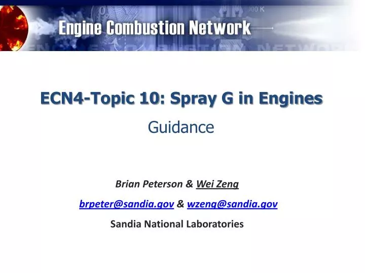
ECN4-Topic 10: Spray G in Engines Guidance. Brian Peterson & Wei Zeng brpeter@sandia.gov & wzeng@sandia.gov Sandia National Laboratories. Motivation. 300 rpm. 2000 rpm. Swirl flow direction. 600 us ASOI (-19.0 ᵒ CA) 600 us ASOI (-11.4 ᵒ CA).

E N D
ECN4-Topic 10: Spray G in Engines Guidance Brian Peterson & Wei Zeng brpeter@sandia.gov & wzeng@sandia.gov Sandia National Laboratories
Motivation 300 rpm 2000 rpm Swirl flow direction 600 us ASOI (-19.0 ᵒCA) 600 us ASOI (-11.4 ᵒCA) 100 us ASOI (-22.0 ᵒCA) 100 us ASOI (-17.4 ᵒCA) 150 us ASOI (-19.9 ᵒCA) 150 us ASOI (-16.8 ᵒCA) 200 us ASOI (-19.8 ᵒCA) 200 us ASOI (-16.2 ᵒCA) 250 us ASOI (-19.7 ᵒCA) 250 us ASOI (-15.6 ᵒCA) 300 us ASOI (-19.6 ᵒCA) 300 us ASOI (-15.0 ᵒCA) 350 us ASOI (-19.5 ᵒCA) 350 us ASOI (-14.4 ᵒCA) 400 us ASOI (-19.4 ᵒCA) 400 us ASOI (-13.8 ᵒCA) 450 us ASOI (-19.3 ᵒCA) 450 us ASOI (-13.2 ᵒCA) 550 us ASOI (-19.1 ᵒCA) 550 us ASOI (-12.0 ᵒCA) 650 us ASOI (-18.9 ᵒCA) 650 us ASOI (-10.6 ᵒCA) 700 us ASOI (-18.8 ᵒCA) 700 us ASOI (-10.0 ᵒCA) 750 us ASOI (-18.7 ᵒCA) 750 us ASOI (-9.4 ᵒCA) 800 us ASOI (-18.6 ᵒCA) 800 us ASOI (-8.8 ᵒCA) 850 us ASOI (-18.5 ᵒCA) 850 us ASOI (-8.2 ᵒCA) 900 us ASOI (-18.4 ᵒCA) 900 us ASOI (-7.6 ᵒCA) 950 us ASOI (-18.3 ᵒCA) 950 us ASOI (-7.0 ᵒCA) 50 us ASOI (-22.1 ᵒCA) 50 us ASOI (-18.0 ᵒCA) 500 us ASOI (-19.2 ᵒCA) 500 us ASOI (-12.6 ᵒCA) SOI (-23 ᵒCA ATDC) • Spray development (late injection) in a DISI engine • At 2000 rpm, liquid jets quickly collapse and rotate with the swirl flow • Demonstrate the influence of intake-generated gas flow on spray development • Different from the spray in constant-volume chamber
Experimental Objectives • The objective is to closely align engine efforts with that of Spray G in constant-volume chambers • Results will be used: • to demonstrate and understand the influence of engine environment (BC’s, local flow, etc.) on spray development • to compare with Spray G results obtained from measurements in constant-volume chambers • to check the reproducibility of the measurements between facilities, operating conditions, injectors and engines (boundary conditions verification) • as input data for model development
Experimental conditions for Spray G • Three experimental conditions for constant-volume chambers have been proposed by Spray G group • The engines should be operated at timings (crank-angle) necessary to obtain thermodynamic environments that are similar to the Spray G2&G3 conditions Parameter Spray GSpray G2Spray G3 Late injection Early injection Early injection • Flash boiling Non-flash-boiling • Fuel Iso-octane Iso-octane Iso-octane • Fuel pressure 20 Mpa 20 Mpa 20 MPa • Fuel temperature 90ᵒ C 90ᵒ C 90ᵒ C • Injector temperature 90ᵒ C 90ᵒ C 90ᵒ C • Ambient temperature 300ᵒ C20ᵒ C * 20ᵒ C • Ambient density 3.5 kg/m30.6 kg/m3 1.12 kg/m3 (Pressure - Nitrogen) (600 kPa)(53 kPa) (100 kPa) • Injected quantity 10 mg 10 mg 10 mg • Number of injections 1 1 1 * It is difficult to achieve in the engine, therefore room temperature is recommended, as shown in slide 7
Target of engine group for ECN4 • The primary goal is to finish early injection conditions before ECN4 • Spray G2 (flash-boiling) and G3 • A flat optical piston is recommended for early injection conditions • Late injection is also recommended • The guidance will be added shortly Parameter Spray GSpray G2Spray G3 Late injection Early injection Early injection • Flash boiling Non-flash-boiling • Fuel Iso-octane Iso-octane Iso-octane • Fuel pressure 20 Mpa 20 Mpa 20 MPa • Fuel temperature 90ᵒ C 90ᵒ C 90ᵒ C • Injector temperature 90ᵒ C 90ᵒ C 90ᵒ C • Ambient temperature 300ᵒ C60ᵒ C 60ᵒ C • Ambient density 3.5 kg/m30.5 kg/m31.0 kg/m3 (Pressure - Nitrogen) (600 kPa)(50 kPa) (100 kPa) • Injected quantity 10 mg 10 mg 10 mg • Number of injections 1 1 1
Engine operation (proposed) • Operation parameters (similar to spray G2&G3) • Fuel: iso-octane • Injection pressure: 20 MPa / Central injection • Coolant temperature: 90ᵒ C • Oil temperature: 90ᵒ C • Injection quantity: 10 mg • Number of injections: 1 • Operation strategy: Motored operation with skip7-injection1* • Operation strategy can be changed to keep the fuel temperature close to 90ᵒ C • Above-mentioned parameters for spray operation should be consistent for all groups * To maintain fuel temperature for flash-boiling
Engine operation (proposed) • Specific thermodynamic surroundings • Average intake pressure: 53 kPa, 100 kPa • Injection timing: Injection in early intake stroke (likely between -300° to 270 ° CA ATDC ) but slightly different between groups • In-cylinder pressure trace depends on engine • Injection timing should be varied to ensure that the in-cylinder pressure is close to 53/100 kPa when fuel is injected. • Sandia DISI engine shows that the in-cylinder pressure of 53 kPa can be achieved around -300° to 270 ° CA ATDC when intake pressure is set to 53 kPa
Engine operation (proposed) • Unique thermal surroundings • Intake air temperature: Room temperature • It is challenging for most of engine groups to control the in-cylinder air temperature at 20ᵒC • Therefore, intake air at room temperature is recommended. • This means when fuel is injected ambient temperature will be higher than 20°C, but this is unavoidable. (Does this affect flash-boiling? May need flash-boiling condition at a ambient temperature higher than 20°C) • Estimation of ambient temperature at injection timing is recommended. • Unique flow dynamic environment • Engine speed: 1000, 2000, 300 (recommended) rpm • 2000 rpm is preferable because it shows stronger flow impact on spray development • Low engine speeds (300 rpm, thus weak flow effect) is recommended for comparison with near-quiescent constant-volume chamber measurements • Flow generation: Unique (facility-specific) • Stage of engine flow development will be different, but this is unavoidable • On the other hand, it is useful to characterize the spray under various fluid dynamic environments (tumble, swirl, squish and turbulence level) • Characterizing the in-cylinder gas flow generation is recommended
Nozzle-hole labeling • Use electric connector to label the nozzle hole • Two possible relative locations • The nozzle hole is labeled as 1, 2, 3 … 8. • Approach: the closest hole is labeled as the first one. 5 5 6 4 4 6 7 3 3 7 8 2 8 2 1 1 The counterclockwise labeling direction is determined by looking at the injector tip Electric connector Electric connector Location 1: Location 2:
Spray position • Position 1 is required, but position 2 is also recommended. Spark plug Spark plug Spray-plume Spray-plume Position 1: one plume hits the spark plug (assume imaging through piston bowl window) Position 2: spark plug is in between two plumes
Diagnostics • The optical access for each engine is unique. Each group should consider appropriate techniques and camera views for spray measurements. • Here, the goal is to obtain the macro-spray development and vaporization in the engine, including • Liquid-phase structure • Mie-scattering (with head or side illumination) technique is recommended • Vapor-phase structure • Schlieren (if possible) or laser-induced-florescence (LIF) technique is recommended • Quantified vapor concentration (recommended) • PLIF technique is recommended (need further discussion, such as tracer) • Spray groups normally use simultaneous Schlieren and diffused back-illumination (or Mie-scattering) to get the liquid- and vapor-phase penetrations. This is recommended if possible. • PIV for flow characterization is recommended if possible.
Data needed from experimentalists • Quantitative results (recommended) • Imaging through optical cylinder: liquid and vapor penetrations vs. time • Imaging through piston bowl window:liquid and vapor widths, and jet axial penetration (if applicable) vs. time • For vapor width, full-width at half max in the mean concentration field is recommended • Flash-boiling normally causes spray collapse. Some specific definitions are recommended to quantify the collapse. (need further discussion) • Cyclic variation (due to flow variations) is a important nature for DISI engine. Quantification of spray variations from cycle-to-cycle is also recommended. • Pre-injection intake-induced gas flow generation (if any)
Groups and potential start date • Experiments • Sandia DISI engine lab (Magnus Sjöberg) • -January, 2015 • University of Duisburg-Essen (Sebastian Kaiser) • -February, 2015 • TU Darmstadt (Benjamin Böhm) • -April, 2015 • University of Michigan (Mohammad Fatouraie, Margaret Wooldridge) • -October, 2014 • Shanghai Jiao Tong University (Min Xu, David Hung) • - • Sandia LTGC lab (John Dec) (Potential) • Simulation • GM (Potential)
Advertisement for simulation • It is important to examine your model under real engine conditions • Simulation for each of these three conditions is welcome. Parameter Spray GSpray G2Spray G3 Late injection Early injection Early injection • Flash boiling Non-flash-boiling • Fuel Iso-octane Iso-octane Iso-octane • Fuel pressure 20 Mpa 20 Mpa 20 MPa • Fuel temperature 90ᵒ C 90ᵒ C 90ᵒ C • Injector temperature 90ᵒ C 90ᵒ C 90ᵒ C • Ambient temperature 300ᵒ C60ᵒ C 60ᵒ C • Ambient density 3.5 kg/m30.5 kg/m31.0 kg/m3 (Pressure - Nitrogen) (600 kPa)(50 kPa) (100 kPa) • Injected quantity 10 mg 10 mg 10 mg • Number of injections 1 1 1
Expectations for injector usage • As a user of an ECN Spray G injector, I agree to: • Ensure that my fuel system is clean and free of particles. • Use available Delphi “setup” injectors of the same type to ensure pressure and injector driver controls are functional, prior to installation of a Spray G injector. • Apply active cooling to the injector at all times to the target temperature to ensure that it does not overheat. • Prevent water condensation (and eventual rust/oxidation) and coking by purging of vessel with dry air or nitrogen. • Coating the nozzle with a light oil (or WD-40) after experiments are completed to prevent oxidation when in storage. • Measure ambient and injector temperature (and composition) boundary conditions to ensure that target conditions are met. • Provide relevant vessel or engine intake geometry to permit CFD simulation of the experiment. • Share results to the ECN archival website following instructions on the participation page.