Download
1 / 31
310 likes | 423 Vues
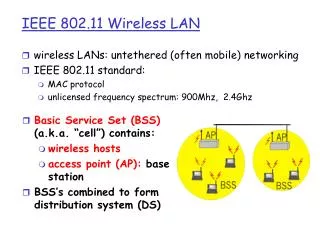
TMTC MCSE S. T. LIANG. Protecting IEEE 802.11 Wireless LANs against the FCS False Blocking Attack. Shih-Tsung Liang* and Ming-Yi Weng ** *Department of Mathematics Computer Science Education, Taipei Municipal Teachers College

E N D
TMTC MCSE S. T. LIANG Protecting IEEE 802.11 Wireless LANs against the FCS False Blocking Attack Shih-Tsung Liang* and Ming-Yi Weng** *Department of Mathematics Computer Science Education, Taipei Municipal Teachers College **Department of Computer Science and Information Engineering, Da-Yeh University
IEEE 802.11 Media Access Control The FCS False Blocking Attack FCS False Blocking Detection and Recovery Numerical Results Concluding Remarks Outline
DIFS Contention Window Busy Backoff Next Frame Medium Window Slot Time Select random backoff time (in slot) and decrementas long as medium is idle to transmit a frame when the medium is busy IEEE 802.11 Media Access Control • IEEE 802.11 DCF (Distributed Coordination Function) DIFS Medium is idle to transmit a frame after long period of idle medium
EIFS Contention Window Busy Backoff Next Frame Medium Window Slot Time Select random backoff time (in slot) and decrementas long as medium is idle to transmit a frame when the medium is busy IEEE 802.11 Media Access Control • On receiving an FCS error frame EIFS Medium is idle • to give high priority to the retransmission of FCS-error frames • In case of the false CRC module in the receiving site, the longer holdback can deter the malfunctioning station from transmitting error frames, and hence prevent the waste of bandwidth to transmit a frame after long period of idle medium
DIFS Contention Window Busy Backoff Next Frame Medium Window Slot Time Select random backoff time (in slot) and decrementas long as medium is idle to transmit a frame when the medium is busy IEEE 802.11 Media Access Control • After an error-free frame being received DIFS Medium is idle to transmit a frame after long period of idle medium
The FCS False Blocking Attack • A station constantly transmits frames with FCS error Attacking station (DIFS) Wireless bandwidth the attacking station can get higher priority to transmit Contending Other stations nearby (EIFS)
The FCS False Blocking Attack • Impact of the FCS False Blocking attack on network performance (traffic volume) + -
Possible solutions? How about to identify the attacking source? The MAC address matching process may take much more time than FCS calculation The identified MAC address may be a fake FCS error frames still coming from malicious attackers Our approach Does not identify the source Frustrates the malicious behavior The FCS False Blocking Attack
FCS False Blocking Detection and Recovery • The ratio of error_frames to correct_frames error_frames/correct_frames no. of stream video connections
FCS False Blocking Detection and Recovery frame received rcv_frame++ FCS correct? N Y Data Collection Phase error_frame++ correct_frame++ N rcv_frame>detection_count? return Y
FCS_error_flag=0? error_frame/correct_frame >error_threshold && rcv_frame≠error_frame? error_frame/correct_frame <error_threshold FCS False Blocking Detection and Recovery N Y N Y Y Detection and Recovery Phase FCS_error_flag=0 Set IFS to EIFS N FCS_error_flag=1 Not Set IFS to EIFS error_frame=0 correct_frame=0 all_frame=0 return
data data data FCS error attack source data Numerical Results • Simulation set up • Based on Network Simulator v2.27 • Embed the proposed FCS False Blocking detection and recovery mechanism into the 802.11 MAC module of NS2.27 (C++ code implementation) • network topology • FCS error attack source • Constant bit rate • streaming video connections • 150Kbps/300Kbps
Numerical Results • Simulation parameter settings
Numerical Results Scenarios I, II
Numerical Results Scenarios III, IV
Identify a new pattern of 802.11 false blocking attacks—the FCS false blocking attack, in which the attacker continuously transmits data with erroneous FCS values Corresponding detection and recovery mechanism is also proposed and has shown to be able to moderate the impacts to the wireless networks caused by FCS false blocking attacks Under a single attacking source, the FCS False Blocking detection and recovery mechanism can averagely increase the network throughput 5% to 8% Concluding Remarks
Thank you!! Request for Comment
CSMA/CA Error Recovery Mechanisms DCF Access Procedure DCF
Why CSMA/CD doesn’t work? The hidden terminal problem! CSMA/CA STA1 STA2 STA3 STA1can communicate with only STA2. STA2 can communicate with STA1and STA3. STA3 can communicate with only STA2. The frame from STA1to STA2 can be corrupted by a transmission initiated by STA3. The STA3 did not know the ongoing transmission from STA1to STA2
To cope with the hidden terminal problem Medium reservation through the exchange of RTS and CTS frames prior to the actual data CSMA/CA RTS CTS STA2 STA3 STA1 Area cleared by RTS (Request To Send) Area cleared by CTS (Clear To Send)
MAC-Level Acknowledgement Wireless media are noisy and unreliable The source needs to make sure the frame has been correctly received by the destination If the source does not receive the ACK, the source will retransmit the frame CSMA/CA
4-way MAC frame exchange protocol CSMA/CA Source Destination RTS Collision Protect!! CTS who protect me? (size is the key!!) Data ACK
More about 4-way handshake RTS and CTS may be disabled by the dot11RTSThreshold attribute in the MIB (Management Information Base) If frame length > dot11RTSThreshold → 4-way frame exchange with RTS and CTS If frame length≤dot11RTSThreshold → frame exchange without RTS and CTS The defaultdot11RTSThresholdis 128 In environments STAs can hear from each other, a higher dot11RTSThreshold can reduce the bandwidth consumption on RTS and CTS CSMA/CA
Carrier Sense Mechanism Physical carrier sense Physical layer carrier sense Similar to 802.3 Check for Medium status (Idle/Busy) Virtual carrier sense Mac layer carrier sense Network Allocation Vector (NAV) A countdown counter to record the amount of time remains before wireless channel clear (i.e. NAV=0→clear) CSMA/CA
MAC control logic CSMA/CA Wait for frame to transmit NAV=0 ? Flag=0 Flag=1 Note: The period of time immediately following a busy medium is the highest probability of collision ccurring. Many stations may be waiting for the medium to become idle and attempt to transmit at the same time. Thus whenever the station sensing a busy medium, a random backoff time is used. Check PHY N Medium Idle? Y Collision ? N Y Wait IFS Transmit Frame Flag==0 ? Still Idle ? N Y Y N Random Backoff Time
CSMA/CA • Random backoff time • Backoff time=Random()*aSlotTime • Random():a uniform distributed integer randomly selected from [0,CW], where CW is contention window • For each unsuccessful frame transmission, CW doubles (from CWmin to CWmax) • CW 2 CW+1 • Reduces the collision probability
Error Recovery Mechanisms • Errors (interference, collision) • STA sends an RTS but not receive the CTS • STA sends a data frame but not receive the ACK • Retransmission with retry limit • shortRetryLimit : frame length≤dot11RTSThreshold • longRetryLimit : frame length > dot11RTSThreshold
DCF Access procedure • Interframe space (IFS) • SIFS: Short InterFrame Space • Used for immediate response actions (e.g., ACK, CTS) • PIFS: PCF InterFrame Space • Used by centralized controller in PCF scheme when using polls • DIFS: DCF InterFrame Space • Used by distribution coordination function (DCF) for asynchronous frames contention • EIFS: Extended InterFrame Space • Used by the DCF after indication of the erroneous frame (e.g., FCS error) • Reception of an error-free frame during the EIFS causes the access using EIFS is terminated and normal medium access (using DIFS) continues shortest longest
DIFS Immediate access when medium is free >= DIFS Contention Window PIFS DIFS SIFS Busy Backoff Next Frame Medium Window Slot Time Defer Access Select Slot and decrement backoff as long as medium is idle DCF Access procedure • Basic Access Method
DCF Access procedure • Example of backoff procedure DIFS DIFS DIFS backoff=12 backoff=7 backoff=3 busy STA 1 backoff=5 busy STA 2 DIFS busy STA 3 backoff=9 backoff=4 busy STA 4 • After MSDU arriving at MAC, STA 3 senses medium free for DIFS, so it initiates transmission • immediately without backoff interval • For STA 1,2, and 4, their DIFS intervals are interrupted by STA 3. Thus, the backoff • Intervals for STA 1, 2, and 4, are generated randomly (e.g., 12, 5, and 9, respectively) • After transmission of STA 2, the remaining backoff interval of STA 1 is (12-5) = 7. • After transmission of STA 2, the remaining backoff interval of STA 4 is (9-5) = 4. • After transmission of STA 4, the remaining backoff interval of STA1 is (7-4) = 3.
DCF Access procedure • Example of backoff procedure (continue) DIFS DIFS DIFS backoff=9 backoff=4 busy STA 1 backoff=5 backoff=20 backoff=16 busy STA 2 DIFS busy STA 3 backoff=5 backoff=18 backoff=14 busy busy STA 4 • STA 3 senses medium free for DIFS and initiates transmission immediately • For STA 1,2, and 4, their DIFS intervals are interrupted by STA 3. Thus, the backoff • Intervals for station 1, 2, and 4, are generated randomly (e.g., 9, 5, and 5, respectively) • Collision occurs between STA 2 and 4. • After the collision of STA 2 and 4, the remaining backoff interval of station 1 is (9-5) = 4. • The backoff Intervals for retransmission of STA 2, and 4, are generated randomly (e.g., 20 and 18, respectively). (tend to be larger the initial attempt)