Download
1 / 26
300 likes | 438 Vues
Probe Measurements of Electron Energy Distributions in Gas Discharge Plasmas V. A. Godyak 1 and V. I. Demidov 2 1 RF Plasma Consulting, Brookline, MA 02446, USA 2 West Virginia University, Morgantown, WV 26506, USA . Electron Distribution Function f. , .

E N D
Probe Measurements of Electron Energy Distributions in Gas Discharge Plasmas V. A. Godyak1 and V. I. Demidov2 1 RF Plasma Consulting, Brookline, MA 02446, USA 2West Virginia University, Morgantown, WV 26506, USA
Electron Distribution Function f , Two-term approximation (small anisotropy, f1 << f0)
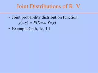
Electron Energy Distribution (EEDF) andElectron Energy Probability (EEPF) Functions F(t,r ε) = 4 .
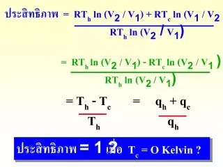
Langmuir formula and Druyvesteyn method Similarly, all plasma parameters (Tesk, λD, JB) and rates of plasma-chemical processes (νea, νee, ν*, νi, ….) can be found as appropriate integrals of the measured EEPF.
What makes a good EEDF measurement? • We want to have more than Langmuir method gives us • EEDF has to resolve tail electrons (ε>ε*) responsible for excitation, ionization and electron escape, as well as low energy electrons (ε< Te) accounting the majority of electrons • Due to error augmentation inherent to differentiation procedure, small (invisible) inaccuracy in Ip(V) can bring enormous distortion in the measured EEDF • It is important to realize the source of the possible errors and to be able to mitigate them. • The sources of the errors are well elucidated in the literature, but are insistently ignored in the majority of published papers.
Problems in probe measurements and their mitigations. • Probe size: a[ln(πl/4a)], b, λD << le and Ip << Id, Ir, Iz • Ir = IB = ScheNsvB, vB = (Te/M)1/2,,,,,..Iz = eΓe is the current corresponding to generation rate of electrons with energy ε in the volume defined by the chamber characteristic size Λ, or by the electron relaxation length λε, • To neglect the voltage drop across the wall sheath, the following requirement has to be satisfied: • (SpN0/SchNs)(M/2πm)1/2 << 1 a = 38 μm b = 175 μm
Probe constructions P1 P2 a = 0.05 mm, b = 1 mm, c = 2-3 mm
EEPF Druyvesteynization due to Rc δ = Rc/Rpmin Rpmin= Te/eIesat Error in EEPF less than 3% requires Rc/Rpmin < 0.01 !
Example of EEPF measurement in argon ICP with a low disturbance probe having Rc and noise compensation Maximal argon pressure, where measurement was possible, was limited by the chamber surface ,
Argon, 20 mTorr VGPS: emax = 15-22 eV νee ∞ NTe-3/2 Maxwellization Argon, 20 mTorr Espion: emax = 7-11eV “Druyvesteynization”” Distorted @ low energy and lost information @ high energy Comparison of EEPF measured with different commercial probe stations At maximal discharge power of 2 kW, N ≈ 1·1012 cm-3,thus EEPF has to be Maxwellian
In a high density plasmas, EEPF at low energy must be Maxwellian
RF plasma potential Criterion for undistorted by rf sheath voltage EEPF measurement is known for over 30 years (1979) Zpr/Zf ≤ (0.3-0.5)Te/eVplrf A presence of a filter in the probe circuit does not guarantee undistorted EEPF measurement. To do the job, the filter has to satisfy the following condition for all relevant harmonics: Zf ≥ (2-3)ZpreVplrf /Te For filter design we need to know (measure!)Vplrf and minimize Zpr
Filter design procedure Zpr is defined by its sheath capacitance at floating potential
Probe measurement circuit incorporating, dc voltage and low frequency noise suppression, rf compensation and rf filter dc resistance compensation with I/V converter having a negative input resistance
Example of EEPF measurement demonstrating a paradoxical Te distribution in argon 13.56 MHz CCP 30 mTorr, Teo < Tes 300 mTorr, Teo > Tes
EEPF and plasma parameters evolution during CCP transition to the γ- mode
Time resolved EEPF measurements EEPF measured in afterglow stage of ICP with internal ferrite core inductor
EEPF and Te measured along rf period in an induction lamp operated at 300 mTorr Ar and 7 mTorr Hg Time resolution δt = 0.5 μS. Note asymmetry in Te(ωt) Probe sheath capacitance to plasma is the main limiting factor in EEPF measurement speed. The minimal time resolution, δt > (10-30)ωpi
Ion current effect Ip = Ie + Ii and I”p = Ie”+ Ii” Ion current effect occurs in light gases, low density plasmas and small probes, and is maximal at orbital ion motion (a/λD < 1), according to: Ie”/Ii” = (4πM/m)1/2η3/2exp(-η)η = eV/Te independently ona/λD In practice, Ii” effect is essentially smaller and can be neglected Ratio Ie”/Ii” depends on EEPF and a/λD
Relative Ii” effect for orbital and radial ion motion for Maxwellian and Druyvesteyn distributions Ie”, Ii”, Ip” Orbital motion Radial motion Hydrogen a/λD 1.0 10 100 eV/kTe
Accounting for Ii” contribution In many works and commercial probe instruments, the extrapolated from large negative probe potential Ii(V) is subtracted from Ip(V) with following differentiation. Due to uncertainty of the extrapolation and error augmentation caused by differentiation this way of accounting for Ii” brings more error than correction. • Ion probe theories used in probe diagnostics do not account for: • Non-Maxwellian EEDF • Rear collisions that destroy OM • Two-dimentionality of the probe sheath • Ambipolar ion drift (Va >> VTe) • Plasma parameters found from Ii(V) may be up to an order of magnitude differ from those found from Ie(V)!
Probe surface effects I”p(V) Φwf (Volt) Ne + 5% benzyl Mo Ta W Ar
Probe surface effects: • Probe surface work function (changes during probe scan) • Non conductive layer of reaction product → (Rc) • Sputtering of electrode and probe and deposition conductive layer on the probe holder → Sp • Strong temperature dependence of all above • REMEDIES • Continuous probe cleaning with fast probe scan (mS) • Ion bombardment, electron heating and rf biasing • Probe cleaning before or after probe scan is ineffective
EEPF measurements with VGPS in Plasma reactors (Wide specter and large amplitude of rf plasma potential and high rate of probe contamination are the major problems) Microcrystalline silicon deposition H2/CF4 30 mTorr ICP with Ar/SiF4 10 mTorr ECR. polymer deposition. Ecole Polytechnique University of Maryland
A remark Today, plasma simulation codes are practically main tool for study plasma electrodynamics, plasma transport and plasma kinetics in commercial plasma reactors. These codes applied to complicated processing gas mixture are missing many cross sections for variety of (accounted and not) plasma-chemical reactions. They also are missing effects of nonlocal and nonlinear plasma electrodynamics that has been proved can be important and even dominant in rf plasmas at low gas pressure. In such situation, a feasibility of EEDF measurement in plasma chemical reactors would give a valuable experimental data for understanding variety of kinetic process in such plasmas and validation of existing numerical codes.