Download

1 / 15
150 likes | 372 Vues
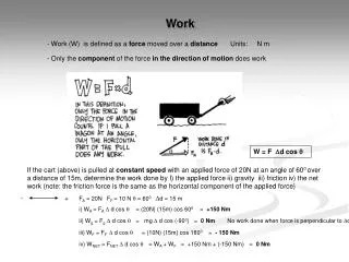
Work Points, Work Axes, and Work Planes. Work Points. Work point Independent entity Location is defined in space May be placed or projected onto part faces, linear edges, or onto an arc or circle Can be constrained to center points of arcs, circles, and ellipses. Work Axis. Work axis

E N D
Work Points • Work point • Independent entity • Location is defined in space • May be placed or projected onto part faces, linear edges, or onto an arc or circle • Can be constrained to center points of arcs, circles, and ellipses
Work Axis • Work axis • Line extending forever in two directions • Useful for locating the center of a hole or cylinder • Used to create revolved features • May be constrained in assembly models
Work Axis Through Two Points • Initiate a work axis • Select two points on an object • Points may be existing corners or midpoints
Work Planes • Work planes • Continuous two-dimensional planes • Can be used to establish sketch planes • Assembly constraints can also be applied to work planes
Applying Work Planes • Work plane can be placed on an existing part face • Work plane feature is initiated • Surface is selected
Offsetting a Work Plane • Initiate work plane feature • Click, hold, and drag the cursor on an existing flat part surface • Identify desired offset distance
Attaching a Sketch Plane • Create sketch plane and sketch geometry
Angled Work Planes • Initiate work plane • Click on an EDGE • Select reference surface • Enter angle • Rotate angle CCW from reference surface
Angled Work Planes • Angled work plane may be established by selecting two parallel EDGES
Angled Work Planes • Angled work plane may also be established by selecting three corners or midpoints on an existing object(s)
Tangent Work Planes • Select cylindrical surface close to area where work plane should be tangent • Identify original plane in origin folder that the new work plane should be parallel to
Work Planes Through a Cylinder • Initiate a work axis • Select cylinder’s curved surface for placement • Initiate a work plane • Select work axis in cylinder • Select principle plane in origin folder and enter reference angle
Work Planes Through a Cylinder • Initiate a work axis • Place it by selecting cylinder’s curved surface • Initiate work plane • Select work axis in cylinder • Select a principle plane in the origin folder and enter a reference angle
Work Planes Between Work Planes • Create work plane through two parallel edges • Offset second work plane an appropriate distance away • Create third work plane between the first two by selecting both in any order