Download
1 / 8
100 likes | 268 Vues
Integrated Front-end Receiver. Satellite Digital Audio Radio Service (SDARS) Team: Wireless Moguls. Members: Advisor: Yuriy Miroshnichenko Dr. Thomas Weller Peter Kowalik. Functional Description. T - DARS Terrestrial Repeaters S - Satellite DARS Bands

E N D
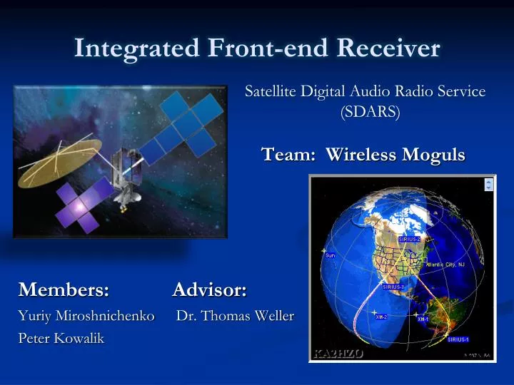
Integrated Front-end Receiver Satellite Digital Audio Radio Service (SDARS) Team: Wireless Moguls Members: Advisor: YuriyMiroshnichenko Dr. Thomas Weller Peter Kowalik
Functional Description • T - DARS Terrestrial Repeaters • S - Satellite DARS Bands • Operated by XM Radio & Sirius • 2.3-GHz S Band: 2320 to 2345 MHz • Channel Bandwidth 12.5 MHz Frequency (MHz) Project: To design, fabricate, test, and measure of an integrated front-end receiver for the Satellite Digital Audio Radio Service. Goal: To receive the SDARS low-power satellite signals as well as terrestrial signals utilizing multiple components, and test the receiver by using a tuner currently available in the market.
System Block Diagram SDARS Input Signal Active Antenna
Passive Antenna Element Requirements Proposed design: Turnstile antenna • Left hand circular polarization (LHCP) • Unity gain or better Radiations Pattern
Low Noise Amplifier (LNA) Requirements Proposed design • Low noise figure less then 1dB Typical. • 5V input Voltage • 30mA max current
Bandpass Filter Requirements Filter Connection Schematic • High out of band rejection • Low insertion loss less then 2dB Specifications Freq (MHz) Insertion Return loss 2300.0 1.52 20.04 2340.0 1.48 20.32
Current Progress Status • Prototype • Design Fabrication • PCB Developed • Testing • Z-Matching • Insufficient Gain • Revising • To try Turnstile • Circle Polarization