Download
1 / 48
480 likes | 587 Vues
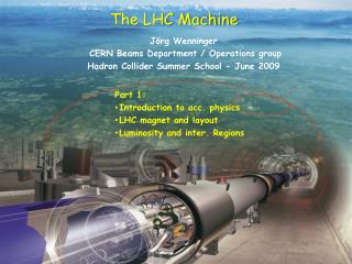
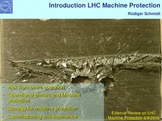
LHC Machine Protection: an introduction . J ö rg Wenninger OP training March 2006. Acknowledgments to my colleagues of the MPWG for input and material. Machine protection at the LHC.

E N D
LHC Machine Protection: an introduction Jörg Wenninger OP training March 2006 Acknowledgments to my colleagues of the MPWG for input and material.
Machine protection at the LHC • Machine protection activities of the LHC are coordinated by the LHC Machine Protection Working Group (MPWG), co-chaired by R. Schmidt & J. Wenninger. http://lhc-mpwg.web.cern.ch/lhc-mpwg/ • Since 2004 the MPWG is also coordinating machine protection at the SPS (ring & transfer lines).
Energy stored in the LHC magnets and beams Charging the energy LHC dipole magnets – quench protection Beam induced damage – what is a safe beam? Beam dumping system Collimation system Strategy for Protection of the LHC machine Outline
Energy stored in the LHC magnets and beams Charging the energy LHC dipole magnets – quench protection Beam induced damage – what is a safe beam? Beam dumping system Collimation system Beam interlock system Outline
Energy stored in a dipole magnet Most energy is stored in the magnetic field of the dipoles Dipole magnet field map for one aperture B = 8.33 Tesla I = 11800 A L = 0.108 H
Energy stored in LHC magnets Approximation: energy is proportional to volume inside magnet aperture and to the square of the magnet field about 5 MJ per magnet Accurate calculation with the magnet inductance: • E dipole = 0.5 L dipole I 2dipole • Energy stored in one dipole is 7.6 MJoule • For all 1232 dipoles in the LHC: 9.4 GJ
Energy stored in the beams 25 ns Stored beam energy: Proton Energy Number of Bunches Number of protons per bunch Proton Energy: 7 TeV In order to achieve very high luminosity: Number of bunches per beam: 2808 Number of protons per bunch: 1.05 ×10¹¹ 3×10¹⁴ protons / beam Stored energy per beam: 362 MJoule
The energy stored in the magnets corresponds to .. an A380 flying at 700 km/h a US aircraft carrier at battle-speed of 55 km/h
The stored energy also corresponds to … 10 GJoule corresponds to… • the energy of 1900 kg TNT • the energy of 400 kg Chocolate • the energy required to heat and melt 12 tons of copper • the energy produced by a nuclear power plant during 10 seconds An important point to determine if there is an equipment damage issue: How fast can this energy be released?
Energy stored in the LHC magnets and beams Charging the energy LHC dipole magnets – quench protection Beam induced damage – what is a safe beam? Beam dumping system Collimation system Beam interlock system Outline
LHC cycle: charging the magnetic energy beam dump energy ramp coast coast 7 TeV start of the ramp injectionphase preparation and access 450 GeV L.Bottura
LHC Powering in 8 Sectors 5 Powering Sector: 154 dipole magnets & about 50 quadrupoles total length of 2.9 km 4 6 DC Power feed LHC 7 3 Octant DC Power 27 km Circumference • Powering Subsectors: • long arc cryostats • triplet cryostats • cryostats in matching section 8 2 1 Sector
Ramping the current in a string of dipole magnet • LHC powered in eight sectors, each with 154 dipole magnets • Time for the energy ramp is about 20-30 min (Energy from the grid) • Time for discharge is about the same (Energy back to the grid) • Note : if you switch off the main dipoles PC, the current decays with a time constant of ~ 6 hours. Power Converter Magnet 1 Magnet 2 Magnet i Magnet 154
LHC cycle – charging the beam energy 7 TeV injectionphase 12 batches from the SPS (every 20 sec) one batch 216 / 288 bunches 450 GeV L.Bottura
Energy stored in the LHC magnets and beams Charging the energy LHC dipole magnets – quench protection Beam induced damage – what is a safe beam? Beam dumping system Collimation system Beam interlock system Outline
Quench A Quench is the phase transition of a super-conducting to a normal conducting state. Quenches are initiated by an energy in the order of mJ • Movement of the superconductor by several m (friction and heat dissipation) • Beam losses • Failure in cooling To limit the temperature increase after a quench • The quench has to be detected • The energy is distributed in the magnet by force-quenching the coils using quench heaters • The magnet current has to be switched off within << 1 second
Operational margin of a superconducting magnet Applied Field [T] quench with fast loss of ~5×10⁶ protons ~ 0.00001% total no. protons/beam Bccritical field Bc 8.3 T QUENCH Tccritical temperature quench with fast loss of ~5×10⁹ protons 0.54 T Tc 1.9 K 9 K Temperature [K]
Quench - transition from superconducting state to normalconducting state - Emergency discharge of energy To limit the temperature increase after a quench • The quench has to be detected : use voltage increase over coil • The energy is distributed in the magnet by force-quenching using quench heaters • The current in the quenched magnet decays is < 200 ms • The current of all other magnets flows through the bypass diode (triggered by the voltage increase over the magnet) that can stand the current for 100-200 s. • The current of all other magnets is dischared inot the dump resistors Power Converter Discharge resistor Magnet 1 Magnet 2 Magnet 154 Magnet i
Energy extraction system in LHC tunnel Switches - for switching the resistors into series with the magnets Resistors absorbing the energy
Detection of quench for all main magnets (1600 magnets in 24 electrical circuits) Detection of quench across all HTS current leads (2000) with very low voltage threshold ~ 1 mV across HTS part Detection of quench in about 800 other circuits Firing heater power supplies, about 6000 units Failure in protection system detection when there is no quench: downtime of some hours no detection when there is a quench: damage of magnet, downtime 30 days Systems must be very reliable Challenges for quench protection
PLC-based Powering Interlock Controllers (PIC) are used to manage the interlock signal between the power converters and the quench protection system. The PIC also interfaces to the Beam Interlock System and will request a beam dump if the electrical circuit that fails is considered to be critical for beam operation. Powering Interlock
Energy stored in the LHC magnets and beams Charging the energy LHC dipole magnets – quench protection Beam induced damage – what is a safe beam? Beam dumping system Collimation system Beam interlock system Outline
A proton injected into the LHC will end its life… • In a collision with an opposing beam proton • The goal of the LHC ! • The experiments are designed to withstand very high particle fluxes and high doses of radiation. • On the LHC beam dump • At the end of a fill, be it scheduled or not. • On a collimator or on a protection device/absorber • The collimators must absorb protons that wander off to large amplitudes to avoid quenches. • Protons that escape the collimation system or are pushed to large amplitudes by a ‘failure’ (operation or equipment). • On the machine aperture • Protons that escape the collimation system…
Beam loss into material Proton losses lead to particle cascades in materials The energy deposition leads to a temperature increase The temperature increase may lead to damage : melting, vaporisation, pressure waves… Magnets could quench….. beam lost - re-establish condition will take hours The material could be damaged….. melting losing performance (mechanical strength) Repair could take several weeks or years ! From SPS we (OP) know by experience that ~ 1013 protons at 450 GeV (1 MJ) we can damage equipment !
Beam induced damage : SPS experiment Controlled experiment: • Special target installed in the TT40 transfer line • Impact of 450 GeV LHC beam (beam size σx/y = 1.1mm/0.6mm) Beam 25 cm
Results…. • TT40 damage test presented by • V. Kain at Chamonix 2005: • Melting point of Copper is reached for an impact of 2.5×10¹² p. • Stainless steel is not damaged, even with 7×10¹² p. • Results agree with simulation A B D C Based on those results the MPWG has adopted for the LHC a limit for safe beams with nominal emittance @ 450 GeV of: 1012 protons ~ 0.3% of the total intensity Scaling the results yields a limit @ 7 TeV of: 1010 protons ~ 0.003% of the total intensity
vaporisation melting Full LHC beam deflected into copper target Copper target 2808 bunches 2 m Energy density [GeV/cm3] on target axis Target length [cm] The beam will drill a hole along the target axis … N.Tahir (GSI) et al.
Beam absorber challenges • The stored energy in the LHC beam is so huge that designing absorbers for the beams that are not destroyed by an impact is a real challenge ! • Almost all protection elements are made of Graphite or other forms of Carbon: very robust low density absorber! • The beam dump block is the ONLY element of the LHC that can safely absorb all the beam – will be discussed in a moment. • All other absorbers in the LHC (collimators and protection devices) can only stand partial losses – typically up to a full injected beam, i.e. equivalent to the energy stored in the SPS at 450 GeV.
Energy stored in the LHC magnets and beams Charging the energy LHC dipole magnets – quench protection Beam induced damage – what is a safe beam? Beam dumping system Collimation system Beam interlock system Outline
LHC Layout IR3, IR6 and IR7 are devoted to protection and collimation ! Beam dump blocks IR5:CMS experiment IR4: Radio frequency acceleration IR6: Beam dumping system IR3: Momentum Collimation (normal conducting magnets) IR7: Collimation (normal conducting magnets) IR8: LHC-B experiment IR2: ALICE experiment IR1: ATLAS experiment Injection Injection
Schematic layout of beam dump system in IR6 Septum magnet deflecting the extracted beam Beam 1 H-V kicker for painting the beam Q5L Beam Dump Block Q4L 15 kicker magnets about 700 m Q4R about 500 m Q5R Beam 2
Dumping the LHC beam beam absorber (graphite) about 8 m about 35 cm concrete shielding
Requirements for a clean dump • Strength of kicker and septum magnets must match the beam energy: • Very safe beam measurement based on the current of the magnets ! • Dump kickers must be synchronized to the « Particle free gap »: • Accurate and reliable synchronization. • Abort gap must be free of particles: gap cleaning with damper. Large graphite absorbers in the beam dump area protect downstream elements (including dump septa themselves) against badly ‘kicked’ particles.
Energy stored in the LHC magnets and beams Charging the energy LHC dipole magnets – quench protection Beam induced damage – what is a safe beam? Beam dumping system Collimation system Beam interlock system Outline
Beam collimation (cleaning) The very high stored energy, combined with a very low thresholds for quench requires a complex two-stage cleaning system: • Large amplitude protons are scattered by the primary collimator (closest to the beam). • The scattered particles impact on the secondary collimators that should absorb them. • The efficiency of the collimation must be larger than 99.9% to be able to run under reasonable conditions, i.e. with lifetimes that can drop down to less than 1 hours from time to time… This requires settings tolerance of < 0.1 mm. 60 collimators/beam!
Beam +/- 3 sigma 56.0 mm Collimators at 7 TeV, squeezedoptics 1 mm Ralphs Assmanns EURO +/- 8 sigma = 4.0 mm Example: Setting of collimators at 7 TeV - with luminosity opticsVery tight settings orbit feedback !!
Prototype collimators Robustness maximized with C-C jaws and water cooling!
Robustness test at SPS Test condition: each jaw hit 5 times! • 450 GeV SPS LHC beam • 3×10¹³ protons • 2 MJ • 1 mm2 beam area • equivalent to: • Full Tevatron beam • ½ kg TNT No sign of jaw damage! (but some deformation was observed on the supporting structures) C-C jaw TED Dump C jaw
Energy stored in the LHC magnets and beams Charging the energy LHC dipole magnets – quench protection Beam induced damage – what is a safe beam? Beam dumping system Collimation system Beam interlock system Outline
‘Unscheduled’ beam loss due to failures Two main classes for failures (with more subtle sub-classes): Passive protection • Avoid such failures (high reliability systems) • Rely on collimators and beam absorbers Beam loss over a single turn during injection, beam dump or any other fast ‘kick’. Active Protection • Failure detection (from beam monitors and / or equipment monitoring) • Fire Beam Dump Beam loss over multiple turns due to many types of failures In case ofany failureorunacceptable beam lifetime, thebeam must be dumpedimmediately, safely into the beam dump block
Beam interlock system Beam ‘Permit’ BIS Dump kicker User permit signals Hardware links and systems Actors and signal exchange for the beam interlock system: • ‘User systems’ : systems that survey equipment or beam parameters and that are able to detect failures and send a HW signal to the beam interlock system. • Each user system provides a HW status signal, the user permit signal. • The beam interlock system combines the user permits and produces the beam permit. • The beam permit is a HW signal that is provided to the dump kicker (also injection or extraction kickers) : absence of beam permit dump triggered !
Beam Dumping System Core of the Machine Protection System User system detects failure Protection for powering operation • Quench Protection System (4000 channels) • Power Interlocking Controller (36 crates for 800 electrical circuits) Protection for beam operation • Beam Loss Monitors System (3500 channels) • Special beam instrumentation (few channels) • Beam Interlock System (16 crates for 150 user connections) • Beam Dumping System (2 complex systems) Beam dump request to Beam Interlock System Beam Interlock System Beam dump request to Beam Dumping System Fire kicker magnets dump beam
LHC protection systems USER_PERMIT SIGNALS BEAM_PERMIT STATUS SIGNALS User System#16 User System #10 User System #8 User System #2 User System #1 User System #9 LHC Injection System for beam 1 BEAM1_PERMIT Beam Dumping System for beam 1 UNMASKABLE INPUTS SPS Extraction System for beam 1 PM event Trigger Timing System LHC Injection System BEAM INTERLOCK CONTROLLER MODULE (BIC) for beam 2 BEAM2_PERMIT Beam Dumping System MASKABLE INPUTS for beam 2 SPS Extraction System for beam 2 to User Systems Mask Settings Safe Beam Flag Schematic of the beam interlock system
Architecture of the BEAM INTERLOCK SYSTEM - fast reaction time (~ ms) - safe - limited no. of inputs - Some inputs maskable for safe beam intensity Beam-1 / Beam-2 areIndependent! Up to 20Users per BIC system: 6 x Beam-1 8 x Both-Beam 6 x Beam-2 • Connected to injection IR2/IR8: • In case of an interlock (=NO beam permit), the beam is dumped & injection is inhibited. • It is not possible to inhibit injection ALONE.
USER_PERMIT signal changes from TRUE to FALSE a failure has been detected… User System process Signals send to LBDS Beam Interlock system process Kicker fired all bunches have been extracted ~70μs max. ~ 89μs > 10μs t1 t2 t4 Achievable response time ranges between 100 s and 270 s (between the detection of a dump request and the completion of a beam dump) BIS reaction times beam dump request Beam Dumping System waiting for beam gap 89μs max t3
Summary The LHC is one of the most complex instruments that has ever been conceived. The LHC is the first accelerator where the machine protection systems are vital. LHC commissioning progress will be strongly influenced by the understanding of the components of the protection systems. The LHC performance will be strongly affected by the protection systems: due to the large number of interlock channels the reliability of the systems must be very high/ Reliability studies have been performed (and there are more to come). The very tight tolerance on machine parameters and collimation will make LHC operation totally different from SPS or LEP: Play once and the beam is gone !