Download
1 / 75
760 likes | 1.02k Vues
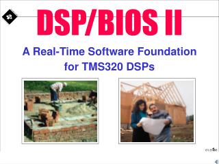
Lecture 04 DSP/BIOS. Chapter 4 DSP/BIOS Part 1 - Introduction. Learning Objectives. Introduce DSP/BIOS and its components. Introduce the software tools for managing DSP/BIOS components and objects. Run some examples. DSP/BIOS. The DSP/BIOS is an operating system that can provide:

E N D
Lecture 04 DSP/BIOS
Chapter 4 DSP/BIOS Part 1 - Introduction
Learning Objectives • Introduce DSP/BIOS and its components. • Introduce the software tools for managing DSP/BIOS components and objects. • Run some examples.
DSP/BIOS • The DSP/BIOS is an operating system that can provide: • A graphical interface for static system setup. • Real-time scheduling. • Real-time analysis (RTA). • Real-time data exchange (RTDX).
DSP/BIOS Components • The user writes code (‘C’/assembly) using the DSP/BIOS library. • The user can use the configuration tools to setup the system. • All the files generated constitute a project.
DSP/BIOS Components • The project is then compiled, assembled and linked by the code generation tools in order to generate an executable file (*.out). • There are also some DSP/BIOS plug-ins that can be used, for instance, as program test while the target is running.
DSP/BIOS Components • Code composer simulator/debugger and the host emulator support are also part of the code composer studio. • The host and target communicate through the JTAG (Joint Test Action Group) connection (ssya002c.pdf).
Graphical Interface for Static System Setup • Static system setup is performed using the DSP/BIOS GUI configuration tool. • The configuration tool has an interface similar to windows explorer. • It lets you: • Specify a wide range of parameters used by the DSP/BIOS real-time library. • Create run-time objects that are used by the target application’s DSP/BIOS API calls. Note: API: Application Programming Interface
Graphical Interface for Static System Setup • The DSP/BIOS main objects are: (1) Hardware interrupts (HWI). (2) Software interrupts (SWI). (3) Tasks (TSK, IDL). (4) Data and I/O streams (RTDX, SIO, PIP, HST). (5) Synchronization and Communication (SEM, MBX, LCK). (6) Timing (PRD, CLK). (7) Logging and statistics (LOG, STS, TRC). For a complete list see: SPRU303.pdf (Page 1-5).
Chapter 4 DSP/BIOS Part 2 - Real Time Scheduling
Learning Objectives • What is a real-time scheduler? • Why do we need a real-time scheduler? • DSP/BIOS Thread Types. • Example.
Real-time scheduling main () { for (;;); } ISR1() { algorithm1(); } ISR2() { algorithm2(); } • Before embarking into real-time scheduling let us first state the problem: • Once ISR1 or 2 is called, algorithm 1 or 2 runs to completion. Can this cause a problem?
Real-time scheduling main () { for (;;); } ISR1() { algorithm1(); } ISR2() { algorithm2(); } • Before embarking into real-time scheduling let us first state the problem: There is no guarantee of meeting the real-time deadlines because: (1) The algorithms can run at different rates. (2) One algorithm can overshadow the other. (3) The timing can be non-deterministic. etc. • Once ISR1 or ISR2 is called, algorithm 1 or 2 runs to completion. Can this cause a problem?
Real-time scheduling • The answer depends on the application. • If we want to process two algorithms in real-time then we have to answer the following questions: • Are ISR1 and ISR2 synchronized? If yes, then we can use only an ISR that processes both algorithms (assuming that we have enough processing power to complete algorithm 1 and 2 on time). • What happens if the algorithms are not synchronized? • Which algorithm has a higher priority? • Can the algorithm of lower priority be pre-empted (stopped)?
Real-time scheduling • Example: Simple application. • System description: • Algorithm 1 and 2 are not synchronised. • Assume algorithm 1 has the highest priority. • Algorithm 2 can be pended. CPU processing Algorithm 1 MISSED! Algorithm 1 Algorithm 2 CPU processing Algorithm 2 • Remember: there is only one CPU and therefore only one algorithm can be processed at a time.
Real-time scheduling Algorithm 1 Algorithm 2 function1 function2 function3 • Example: Simple application. • Solution 1: Algorithm decomposition: • The algorithm can be decomposed into sub-functions: • When the CPU is not processing algorithm1 it can process one of the sub-functions (to completion) as shown: algorithm2 (); function1(); function2(); function3();
Real-time scheduling • Example: Simple application. • Problems with this solution: • Difficult to write (as timing is critical). • Difficult to change (what happens if algorithm is modified or another algorithm is added).
Real-time scheduling • Example: Simple application. • Solution 2: Using an operating system Advantages: • Easy to write (algorithms are written independently). • Easy to maintain or change (operating system takes care of the scheduling). • Enables fast time to market. • Which operating system? Depends on: • The processor being used. • The DSP platform (single/multi processors).
Real-time scheduling: DSP/BIOS • For all TI DSPs there is a DSP/BIOS operating system which includes: • Small sized real-time library. • An API for using the library services. • Easy-to-use configuration tools. • Real-time analysis programs. • DSP/BIOS scheduling solution provides: • Fixed-priority preemptive scheduler. • Multiple thread types.
Real-time scheduling: Terminology No preemption: Resources cannot be preempted; which means that the only way of releasing a resource is by the process of holding it. Object: Term for data and code structures provided by DSP/BIOS, e.g. an event, task, semaphore. Pending: Wait for an event Resource preemption: Release of a resource. Post: Signal an event, e.g. post a software interrupt, that is make a software interrupt ready. Preemption: A higher priority function (or thread) interrupts other functions (or threads) of lower priority. Priority scheduling: Priority scheduling can be either preemptive or non-preemptive. A preemptive priority scheduling algorithm will preempt (release) the CPU if another process of higher priority arrives. Process: A task or thread of execution. Scheduler: System software to manage the execution of threads. Scheduling: The planning used to share a resource. Semaphore: Synchronization system object that enables tasks to synchronize their activities. Thread: An independent function.
DSP/BIOS Thread Types HWI Hardware Interrupts • HWI priorities set by hardware One ISR per interrupt. SWI Software Interrupts • 14 SWI priority levels Multiple SWIs at each level. Priority TSK Tasks • 15 TSK priority levels Multiple TSKs at each level. IDL Background • Multiple IDL functions Continuous loop. HWI triggered by hardware interrupt. IDL runs as the background thread. What causes a SWI or TSK to run?
Triggering SWI or TSK SWI_post SEM_post SWI TSK start SEM_pend block “run to completion” start end end TSK only returns when no longer needed, otherwise normally an infinite loop. SWI cannot pend. SWI always returns from function.
Considerations in Selecting Thread Types • Thread latency and data rates. • Multi-tiered response to interrupts: • HWI is fast (for sample-by-sample response time). • SWI is slower (triggered to process frame). • Priority of thread. • Stack needs: • O.K. to share system stack? then use SWI. • Need private stack? then use TSK. • Synchronization and communication methods: • SWI and TSK have different methods. • User preference or ease-of-use.
Thread Preemption Example post swi1 post swi2 post sem2 post swi2 return return return return post sem1 post sem2 return return return pend sem2 pend sem2 pend sem2 interrupt pend sem1 pend sem1 interrupt interrupt return interrupt HWI SWI 2 SWI 1 TSK 2 TSK 1 main() IDL Events over time
Laboratory Exercise Bios_Lab1 • Laboratory objectives: • Create Project. • Create Configuration File • Set the internal timer 1 to generate ticks at 8kHz. • Set a hardware interrupt (HWI) that is triggered by internal timer 1. • Create a software interrupt (SWI) that can be posted by the hardware interrupt. • Create a task that can be posted by the hardware interrupt. • Create a semaphore (SEM) that can be used by the task functions.
(1) Create New Project • How to create a configuration file: • Open CCS and create a new project and name it “bios_lab_1.pjt”. • Create a new configuration file by using a pre-built template file:File: New: DSP/BIOS Configuration • Double click on the “dsk6416.cdb” icon
(2) Create Configuration File • How to create a configuration file: • After double click on the “dsk6416.cdb” icon the following configuration will appear:
(2) Create Configuration File • How to create a configuration file: • Now that you have selected the .cdb, save it in your current working directory, e.g: MyProjects\BIOS_Lab1\bios_lab.cdb. • Finally, add the “*.cdb” configuration file to the project.
(3) Setting Internal Timer 1 Open CSL – Chip Support Library,and TIMER: • Set a timer configuration by using the “Timer Configuration Manager”. • Right click, “Insert timerCfg” and call it “timerCfg0”. • Right click and set the properties: The GUI interface will generate the “bios_labcfg.c”, see bios_labcfg.pdf
(3) Setting Internal Timer 1 • Open CSL – Chip Support Library,and TIMER: • Click on TIMER Resource Manager • Change Properties of Timer_Device1
(3) Setting Internal Timer 1 • Open CSL – Chip Support Library,and TIMER: • Change Properties of timerCfg0
(4) Setting the Hardware Interrupt (1) In Scheduling session of cdb-API: (2) Select the “HWI - Hardware Interrupt Service …”. (3) Select HWI_INT13 and right click to select properties. Source = Timer_1 Function = _timerIsr
(4) Setting the Hardware Interrupt void timerIsr (void) { /* Put your code here */ } (4) Write the Interrupt Service Routine in C.
(5) Creating a Software Interrupt (1) In Scheduling session select the “SWI - Software Interrupt Manager” and create a new software interrupt called “SWI_for_algorithm_1”. (2) Change the properties of the “SWI_for_algorithm_1” to:
(5) Creating a Software Interrupt void algorithm_1 (void) { /* Put your code here */ } (3) Create a software interrupt function in C.
(6) Creating a Task (Background Task) • Open Scheduling,and TSK - Task Manager: • Insert Task • Click on TSK, change Name to TaskOneTsk • Change Properties
(6) Creating a Task void ProcessTask (void) { /* Put your algorithm here */ } (3) Create a task function in C:
(7) Creating a Semaphore (1) Open the cdb file and select the “SEM - Semaphore Manager” and create a new semaphore called “taskOneSem”. (2) Change the properties of the “taskOneSem” to:
Posting Software Interrupts and Tasks SWI_post (&SWI_for_algorithm_1); SEM_post (&taskOneSem); (1) Software Interrupts The software interrupts can be posted simply by writing: (2) Tasks The task can be removed from semaphore queue and put it on the ready queue:
More on Tasks… void ProcessTask (void) { while (1) { SEM_pend (&taskOneSem, SYS_FOREVER); /* Insert your code here */ } } • A task can be pending where as Software Interrupts (SWI) run to completion. • Tasks normally run in an infinite loop and within the loop the task tests for a semaphore. • A task can preempt itself, e.g:
Putting it all together… void main (void) { /* Put all your setup code here */ return; /*DSP BIOS starts after the return */ } /* Hardware Interrupt */ void timerIsr (void) { /* Put your code here */ SWI_post (&SWI_for_algorithm_1); SEM_post (&taskOneSem); } /*Software Interrupt */ void algorithm_1 (void) { /* Put your code here */ } /* Task */ void ProcessTask (void) { while (1) { SEM_pend (&taskOneSem, SYS_FOREVER); /* Insert your code here */ } }
Putting it all together… void main (void) { /* Put all your setup code here */ return; /*DSP BIOS starts after the return */ } /* Hardware Interrupt */ void timerIsr (void) { /* Put your code here */ SWI_post (&SWI_for_algorithm_1); SEM_post (&taskOneSem); } /*Software Interrupt */ void algorithm_1 (void) { /* Put your code here */ } /* Task */ void ProcessTask (void) { while (1) { SEM_pend (&taskOneSem, SYS_FOREVER); /* Insert your code here */ } }
Putting it all together (main.c)… #include "bios_labcfg.h" #include <std.h> #include <stdio.h> #include <csl.h> #include <csl_timer.h> #include <csl_irq.h> #include <tsk.h> #include <sem.h> void main (void); void algorithm_1 (void); void timerIsr (void); void ProcessTask (void); void main (void) { initApplication (); TIMER_start (hTimer1); return; } void timerIsr (void) {//HWI_INT15 is used to hook to timerIsr () int m=0; int i; /* This can be your critical algorithm */ for (i=1; i<10; i++) m = m+i; /* The end of your critical algorithm */ SWI_post (&SWI_for_algorithm_1); SEM_post (&taskOneSem); } void algorithm_1 (void) {// This is your software interrupt which printf ("The algorithm_1 has been reached \n"); } void ProcessTask (void) {// This is your task - You can reach this task if you comment out the printf in algorithm_1() while (1) { SEM_pend (&taskOneSem, SYS_FOREVER); printf ("The taskOne has been reached \n"); } }
Finalization of the Project • We have Enable HW Interrupt using <initApplication.c> file #include "bios_labcfg.h" #include <csl.h> #include <csl_irq.h> void initInterrupts(void); void initApplication(void) { initInterrupts(); } void initInterrupts(void) { IER |= 0x00002002; /* Enable NMIE and INT13 */ IRQ_enable(IRQ_EVT_TINT1); /* Enable Timer1-to-CPU interrupt */ IRQ_globalRestore(1); /* Enable GIE */ }
Finalization of the Project • Open System: • Click on Global Settings • Change Properties (DSP Speed) to 600MHz
Finalization of the Project • Files used to create the DSP/BIOS program: • The abbreviation 62 is used for the C6000 processors. Programs/Files generated by the configuration manager Programs generated by the user
Finalization of the Project • Files created by the configuration tools: • Once the Bios_Lab1.cdb file is modified, saved and added to the project, the configuration manager will create and load the following files: • Bios_labcfg.s62 Assembly file • Bios_labcfg_c.c C file • Bios_labcfg.h Header file for C • Bios_labcfg.h62 Header file for assembly • A file called “Bios_labcfg.cmd” is also created but must be loaded by the user. Note: the user must add the *.cdb, *.cmd, *.h files to the project.
Chapter 4 DSP/BIOS Part 3 - Real Time Analysis Tools
Learning Objectives • Introduction to the analysis tools. • Using the LOG module. • Using the STS module. • Defining DSP/BIOS objects using the configuration tools. • Example.
Introduction • Traditionally analysis was performed by halting the processor and examining variables or memory. • This traditional method is invasive and does not represent the reality of real-time issues. • Real-time analysis is the analysis of data acquired during real-time operation of a system without having to stop or interfere with the target. • The API’s and Plug-ins provided with DSP/BIOS enable the programmer to monitor data while the target is running.