Download
1 / 55
550 likes | 567 Vues
Learn about the advancements in Next Generation Internet design, focusing on robust scalability and security features. The talk explores BGP basics, routing tables, scaling problems, and proposed solutions.

E N D
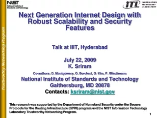
Next Generation Internet Design with Robust Scalability and Security FeaturesTalk at IIIT, HyderabadJuly 22, 2009K. SriramCo-authors: D. Montgomery, O. Borchert, O. Kim, P. GliechmannNational Institute of Standards and TechnologyGaithersburg, MD 20878Contacts: ksriram@nist.gov Trustworthy Networking Program This research was supported by the Department of Homeland Security under the Secure Protocols for the Routing Infrastructure (SPRI) program and the NIST Information Technology Laboratory Trustworthy Networking Program.
BGP Basics SU owns IP address space: 128.230.0.0/16 = 128.230.0.0 - 128.230.255.255 Autonomous System (AS) s1/24 = 128.230.79.0/24 Prefixes s2/28 s3/24 eBPG AS11872 s4/20 s/16 s = 128.230.0.0 s5/24 SU Network (Example) • AS = Autonomous System = A network of routers and hosts • BGP = Border Gateway Protocol • eBGP = external BGP • IGP = Internal Gateway Protocol • Internet is a network of ASes
BGP Basics s1/24 = 128.230.79.0/24 Example of route aggregation s2/28 AS11872 s3/24 b/8 eBPG AS2 s4/20 s/16 s5/24 AS1 a/12 e3/16 s/16 SU Network (Example) e/14 e4/16 AS5 e2/16 c1/18 AS3 c/16 AS4 e1/16 c2/18 d/18 Internet
Functions of BGP • BGP Updates are used to make network reachability announcements: • Announce paths or routes to prefixes • Announce withdrawal of prefixes • Announce path changes • Announce new attributes for a previously announced path Example BGP Path announcement: AS4 - AS1- AS11872 - 128.230.0.0/16 • Each BGP speaker processes received BGP updates: • Computes/updates its best path to the prefix • Or, withdraws the prefix in the event of a withdrawal • Updates the prefix information in its routing table • Propagates its routes to other peers
Routing Tables • Each AS has at least one (may be multiple) BGP routers or speakers • BGP routers connect the AS to other neighboring ASes • BGP routers in different ASes that speak BGP to each other are called peers • A BGP path is a path over one or more ASes to a prefix • Each BGP router receives path information from its neighbors about routes to “announced” prefixes all over the Internet • Each BGP router computes its best path to each prefix and stores that path in the Routing Information Base (RIB) • The BGP router also maintains a Forwarding Information Base (FIB) which is stored on the line card for line speed packet forwarding • The FIB maps each prefix in the table to a next hop router • The FIB and RIB are called routing tables
Routing Table Scaling Problem and Proposed Solutions References:D. Farinacci, V. Fuller, and D. Oran, “Locator/ID Separation Protocol (LISP), IETF ID draft-farinacci-lisp-00.txt, January 2007.X. Zhang et al., “Scaling IP Routing with the Core Router-IntegratedOverlay,” IRTF RRG meeting, March 2007. http://www1.tools.ietf.org/group/irtf/trac/wiki/RRGV. Fuller, “Scaling issues with Routing and multihoming,” IRTF RRG meeting, March 2007. http://www1.tools.ietf.org/group/irtf/trac/wiki/RRGG. Huston and G. Armitage, “Projecting Future IPv4 Router Requirements Trends in Dynamic BGP Behaviour,” Proc. of the Australian Telecommunication Networks and Applications Conference, December 2006.
FIB and RIB Table Growth • The routing table sizes are growing rapidly due to: • Traffic engineering related prefix deaggregation • Multihoming of customer ASes and related deaggregation • Virtual Private Networks (VPNs) • Mobility-related deaggregation • IPv6 deployment (with corresponding Traffic Eng. (TE), multihoming, mobility, etc.) • BGP routers are projected to be unable to keep up with this growth even with upgrades • Such rapid rise has not happened before • Concern: New routers or upgrades could become prohibitively expensive • T-CAM memory in which FIB and route filters (Access Control Lists [ACLs]) are stored are very expensive • New designs for Inter-domain routing protocols are being investigated to keep table sizes manageable for core routers
Some Acronyms • VP: Virtual Prefix (collection of aggregatable prefixes) • TS: Tunnel Startpoint • TE: Tunnel Endpoint • ITR: Ingress Tunnel Router • ETR: Egress Tunnel Router • PE: Provider Edge • PA: Provider Allocated addresses • PI: Provider Independent addresses • EID: End-point ID • LISP: Locator and ID Separation • CRIO: Core Router-Integrated Overlay
a1/16 a2/16 b/8 a/8 a3/16 R1 R2 a4/16 a5/16 a6/16 e/8 a7/16 R5 e2/16 a8/16 R3 c/8 R4 e1/16 a9/16 d/8 A Proposed Solution VP prefix based forwarding Tunneling to TE for this prefix • Solution approach: • Decouple address hierarchy and physical topology • Use Virtual Prefixes (VP) and tunneling • Tradeoff: Reduced routing table size for increased path length (stretch) Packet destined for prefix a7/16
How Do You Bootstrap This • Mapping Distribution Protocol: • This is still work-in-progress (for researchers & industry) • Generate a distribution of VPs and assign them to various VP routers (also called Ingress Tunnel Routers [ITRs]) • Major ISPs (Tier 1 and Tier 2) have to agree to this • Have the ITRs set up the necessary tunnels to appropriate Egress Tunnel Routers (ETRs) • Map-and-Encap – as this approach is generally referred to –mapping followed by encapsulation of end-point ID (inner header) in the tunnel ID (outer header) • Prefix migration scenarios: details of signaling protocol for updating VP mappings – RRG presentation by Sriram et al.
a1/16 a2/16 b/8 a/8 a3/16 R1 R2 a4/16 a5/16 a6/16 e/8 a7/16 R5 e2/16 a8/16 R3 c/8 R4 e1/16 a9/16 d/8 Performance Induced Prefix • An ISP (e.g., Router R4) can have heavy traffic to, say, prefix a8/16 and thus decide to make an exception to VP-based routing and map a shortest-path route in its table. This is called Perf-Induced prefix mapping.
Performance Induced Prefix • Routing table entries for Perf-induced prefix can be entered selectively only for prefixes that collectively carry 80% or 90% of ingress traffic at the router • It is said that top 10% or so of prefixes carry 80% to 90% of the traffic • So the routing table size can still significantly shrink even if perf-induced prefixes are used only for the heavy-traffic prefixes
Local Traffic Not Routed Locally ! Random scheme: • VPs are distributed randomly over the AS-level topology • Packets originating in an AS and destined for an address within the same AS are not detected as such and may be routed to their VP-TS in another AS and then routed back to a TE in the originating AS • Results in increased path length inflation (stretch) • Random+TP and Random+VP enhancements try to address this problem in two different ways (next slide)
Routing Local Traffic Locally Random+TP: (Random + TE-induced prefixes) Random+TP • Every router in each AS maintains routes (internal to the AS) for all its TE-induced prefixes as well as those of other routers in the same AS • Packets originating with in the AS and destined for any of said TE-induced prefixes are routed locally and optimally within the AS AS Alternatively - Random+VP: (Random + VP-TS arrangement) Random+VP • There are one or more VP-TS’s in each AS • Each VP is covered by at least one VP-TS • Each packet originating anywhere in the AS is first routed to the appropriate of the VP-TS • The VP-TS determines if the destination address belongs to a local prefix • Compared to Random+TP case, the internal routing in this case may be sub-optimal, but the table size is smaller VP-TS VP-TS AS
Table Size vs. Path Length Tradeoff Increasing Perf-induced prefixes • Increase the percentage of shortest path traffic by increasing # of Perf-induced prefix entries
Open Issues and Areas for Further Study • Comparative evaluation using simulations of the different proposals that are under study in RRG • Help build security into the address mapping (creation and distribution) protocol which would be a central piece of the new architecture • Security should include authentication of prefix ownership and route originations • Analyze deployment issues (potential consequences during transition) • Study the routing behavior under dynamic conditions, e.g., link and node failures • Investigate methodologies for alternate routing • Help develop a comprehensive set of performance metrics, e.g., table size reduction, path length stretch, stability, and re-convergence time • Identify performance and security trade-offs for making design choices • Study focused overload issues due to extensive use of tunneling • Anticipate and resolve design issues under prefix migration/mobility scenarios • Propose and analyze the details of signaling protocol for updating address mappings.
Part 2:Registry and History (or Monitoring) Data Driven BGP Robustness Algorithms Trustworthy Networking Program
BGP Robustness Problem Space Unauthorized announcement 129.6.*.* AS28 240.18.*.* AS89 NIST (MD) AS49 AS3 AS42 Anomaly/ /// Attack AS701 False origin announcement AS613 NIST (CO) AS2648 AS203 129.6.*.* 129.6.*.* Shortest path to NIST addresses (129.6.*.*) changes for ASes on this side
Data Driven BGP Robustness What are the Data Sources? Addressing Registries global databases of address block and autonomous system number assignments. Routing Registries loosely maintained global databases of contractual relationships for routing services. Monitoring Data public BGP monitoring and measurement projects that collect BGP protocol exchanges at various spots around the Internet. Why is this hard? • Registries • known to be incomplete and inaccurate, and are maintained in differing formats, by differing processes in different regions of the world. • Robustness Algorithms • to be effective, must make precise policy decisions from highly imperfect data. • Needle in a Hay Stack • millions of BGP update messages per day, millions of registry entries, rare but potent threats.
Solution Components Information Synthesis and Quality Analysis (Quality metrics, decision algorithms, privacy, accessibility, availability) Global Route Monitoring (Routeviews, RIPE RIS, PHAS, PCH, CAIDA, Renesys, etc) Measured Data Synthesized Data? Addressing / Routing Registries (ARIN, RIPE, APNIC, AFRINIC, LACNIC, RADBs, etc) DeclarativeData Routing Policies (Alarms, ACLs, BGP filter lists, path preference, parameter tuning). Other Routing Information Services (Bogon lists, etc) Other Info. Global BGP Routing Dynamics
Checking Origin AS : Comparison of Algorithms Registry-based Algorithm Green:Good / FC Light Green: Good / PC Red: Suspicious White: Not found in trace data
Checking Origin AS : Comparison of Algorithms Enhanced trace-data-based Algorithm Green: Good Red: Suspicious White: Not found in trace data
Checking Origin AS : Comparison of Algorithms Enhanced Hybrid Algorithm Green:Good / FC Light Green: Good / PC Red: Suspicious White: Not found in trace data
Part 3:Cert-Based Path Validation Approaches for BGP Updates Trustworthy Networking Program
Origin Only Validation Prefix and AS owners are provided digital certificates of ownership of resources Prefix owner registers which origin ASes can originate the prefix Validation algorithm creates a white list of prefixes and their valid origins
Whole Path Validation Approaches(some candidate options) SPP: Signature Per Prefix No need for Explicit Path Attribute (EPA) Attestation overhead multiplicative with # prefixes in an update SPP-E: SPP with Economization Attestation overhead shared over all prefixes in an update SPP-E-SAS: SPP-E with Sequential Aggregate Signature (SAS) SAS – to be described shortly Attestation size is invariant to # ASes the update goes through SPU-EPA: Signature Per Update with EPA Signature coverage includes announced prefixes and AS path EPAs convey changes made to announced prefix set along the AS path This approach is closest to S-BGP Possible concerns: ISP may be concerned about revealing (in the EPA) about the prefixes they decided not to forward Prefix re-insertion by upstream ASes based on information in the EPAs
Path Validation with Signature Per Prefix (SPP) • Origin AS provides one signature per prefix and the signature covers the prefix and the AS path (including all attributes) • As many signatures in an update as there are prefixes • ASes upstream add their signatures also on a per prefix basis covering individual prefixes together with the modified AS path • AS path predictability works in this case; so there is no need for ExplicitPAs • # signatures = # prefixes in update * # ASes in AS path
Path Validation with One Signature per Prefix Sig 1A Sig 1A Sig 1B Sig 1A Sig 2A Sig 2A Sig 2B Sig 2A Sig 3A Sig 3A Sig 3B Sig 3A Sig 1C Sig 1B Sig 1A Sig 2C Sig 2B Sig 2A Sig 3C Sig 3B Sig 3A Sig 2C Sig 2B Sig 2A Sig 3C Sig 3B Sig 3A Normal case (Example 1): All prefixed are carried through p1 {p1, p2, p3}<B,A> {p1, p2, p3}<A> {p1, p2, p3}<C,B,A> AS-A AS-B AS-C AS-D p2 p3 Special case (Example 2): Possibility of dropped prefixes p1 {p1, p2, p3}<A> {p2, p3}<C,B,A> {p2, p3}<B,A> AS-A AS-B AS-C AS-D p2 Sig 2B Sig 2A p3 Sig 3B Sig 3A • # signatures = # prefixes in update * # ASes in AS path
Path Validation with One Signature per Prefix Sig 1A Sig 2A Sig 2C Sig 2B Sig 2A Sig 3A Sig 3C Sig 3B Sig 3A Sig 4C Sig 4B Sig 4A Sig 5C Sig 5B Sig 5A Sig 4A Sig 4B Sig 4A Sig 5A Sig 5B Sig 5A Special cases (Example 3): Prefixes may be dropped or added {p4, p5}<B,A> {p4, p5}<A> p1 {p1, p2, p3}<A> {p2, p3, p4, p5}<C,B,A> {p2, p3}<B,A> AS-A AS-B AS-C AS-D p2 Sig 2B Sig 2A p3 Sig 3B Sig 3A p4 p5 • # signatures = # prefixes in update * # ASes in AS path
Path Validation with One Signature per Prefix: Signature Sizes for SPP and SPP-E One signature per prefix without overhead economization (SPP) One signature per prefix with shared attestation overhead in each update (SPP-E) (1) (1) …. …. (p) One such extended signature added at each AS along the path (p) Set of p such signatures added at each AS along the path
Path Validation with SPP-E and Sequential Aggregate Signature (SPP-E-SAS) {p4, p5}<B,A> {p4, p5}<A> p1 {p1, p2, p3}<A> {p2, p3, p4, p5}<C,B,A> {p2, p3}<B,A> AS-A AS-B AS-C AS-D p2 Sig 2C* Sig 1A Sig 2B* Sig 3C* Sig 2A p3 Sig 3B* Sig 4C* Sig 3A p4 p5 Sig 5C* Sig 4A Sig 5A Sig 4B* Sig 5B* • In SAS [1], each AS (other than the origin AS) in the path incorporates into its signature the signature from previous AS in a retractable way • Hence, # signatures carried in an update becomes independent of # ASes in AS path • SAS can be applied to any of the proposals we consider here • An overview of SAS is provided at the end (Appendix A) [1] Y. Mu, W. Susilo, and H. Zhu, “Compact sequential aggregate signatures,” Proceedings of the ACM Symposium on Applied Computing (2007), pp. 249-253.
{prefix set 4}<D,C,B,A> p1 {prefix set 3}<C,B,A> {prefix set 1}<A> {prefix set 2}<B,A> AS-A AS-B AS-C AS-D AS-E p2 …. {prefix set 5}<E,D,C,B,A> p3 Collector pn Size estimation of update with attestations received at the Collector: U = Update message size without attestations (bytes) Ua = Update message size with attestations (bytes) p = # prefixes in a prefix set (per update message; p > 1) h = # ASes in an AS path Sig = Signature size (e.g., 40 bytes for DSS; 128 bytes for RSA) Aoh = Attestation overhead (attestation object, signer, sig description, expiry, target) = 39 bytes k = path attribute overhead = 3 or 4 bytes (function of attribute size) m = bytes required to specify # of signatures = 2 bytes (in SPP-E and SPP-E-SAS) Estimation of Update Size with Attestation: SPP, SPP-E, SPP-E-SAS Contd. next page …
{prefix set 4}<D,C,B,A> p1 {prefix set 3}<C,B,A> {prefix set 1}<A> {prefix set 2}<B,A> AS-A AS-B AS-C AS-D AS-E p2 …. {prefix set 5}<E,D,C,B,A> p3 Collector pn Estimation of Update Size with Attestation: SPP, SPP-E, SPP-E-SAS Size estimation of update with attestations received at the Collector: For SPP: Total size of signatures = p*h*(Sig + Aoh + k) bytes Ua = U + p*h*(Sig + Aoh+ k) bytes For SPP-E: Total size of signatures = (p*Sig + Aoh + k+ m)*h bytes Ua = U + (p*Sig + Aoh + k+ m)*h bytes For SPP-E-SAS: Total size of signatures = p*Sig + h*(Aoh + k) bytes Ua = U + p*Sig + h*(Aoh + k) bytes
Path Validation Using Signature Per Update and Explicit Path Attributes (SPU-EPA) {prefix set 4}<D,C,B,A> p1 {prefix set 3}<C,B,A> {prefix set 1}<A> {prefix set 2}<B,A> AS-A AS-B AS-C AS-D AS-E p2 …. {prefix set 5}<E,D,C,B,A> p3 Collector pn • Signature provides coverage over prefixes and AS path • Assume each AS along the path drops some prefixes and thereby makes a change to the prefix set it includes in its repacked update • So each AS along the path has to add an ExplicitPA to the signed update it sends to its next hop neighbor AS • Assume dropping prefixes is allowed but adding them is not allowed (in S-BGP) • This is a conservative approach – because we are not assuming perfect predictability, which happens if the prefix set were not changing along the path – there would have been no need to add ExplicitPA if only this predictability were true
{prefix set 4}<D,C,B,A> p1 {prefix set 3}<C,B,A> {prefix set 1}<A> {prefix set 2}<B,A> AS-A AS-B AS-C AS-D AS-E p2 …. {prefix set 5}<E,D,C,B,A> p3 Collector pn Estimation of Update Size with Attestation: SPU-EPA Size estimation of update with attestations received by the Collector: U = Update message size without attestations (bytes) Ua = Update message size with attestations (bytes) p = # prefixes in a prefix set (per update message) A = Bytes needed to represent an ASN = 4 bytes L = Size of a prefix representation (up to 4 bytes for quad + 1 byte for mask + 1 byte to specify length) h = # ASes in an AS path Sig = Signature size = 40 bytes Aoh = Attestation overhead (attestation object, signer, sig description, expiry, target) = 39 bytes k = path attribute overhead = 3 or 4 bytes (function of attribute size) Total size of ExplicitPAs = Epa = (h-1)*p*L bytes Ua = U + h*(Sig + Aoh) + Epa = U + h*(Sig + Aoh + k) + (h-1)*p*L bytes
RIB Size Modeling • Update sizes with attestations are computed accurately for each of the four schemes (using Routeviews data) • When AS prepending is detected, we collapse the repeated ASes into one AS for the purpose of attestation overhead computation • Projections are made regarding growth in # prefixes in BGP speakers • Suitable modeling assumptions are made regarding other modeling parameters (request BGPSEC team’s feedback / refinements) • The model is highly parameterized and can be tuned to reflect more accurate assumptions or measurements • RIB sizes are estimated and compared for four path validation approaches (others can be included) • Sensitivity to key parameters and assumptions
Update Size with Attestations • We assume DSS with 320-bit signature is used in all method except the SPP-E-SAS method where RSA is used with1024-bit signature in conjunction with SAS • By attestation, we mean the signature bytes and attestation related overhead bytes • The attestation overhead (Aoh) is assumed to be the same (39B) in all cases • When AS prepending is detected, we collapse the repeated ASes into one AS for the purpose of attestation overhead computation • Routeviews Oregon collector; 1.8M updates; Feb. 1-26, 2009
Distribution of Size of Update Announcements Including Attestations(Signature + Overhead)(SPU-EPA) • Prob. {Message < 1200 B} = 99.02% • Prob. {Message < 4000 B} = 99.92%
Comparison of Update Message Size:With and Without Attestations(SPU-EPA) With Attestations Without Attestations • Prob. {Message < 224 B} = 99.00% • Prob. {Message < 854 B} = 99.90% • Prob. {Message < 4000 B} = 99.994% • Prob. {Message < 1200 B} = 99.02% • Prob. {Message < 4000 B} = 99.92%
Distribution of Size of Update Announcements Including Attestations(Signature + Overhead)(SPP-E) Histogram CDF • Prob. {Message < 4000 B} = 97.81% • Prob. {Message < 6792 B} = 99.00% • Prob. {Message < 29044 B} = 99.90 %
Ratio of Update Size for Path Validation Approaches over Current BGP Update Size • We assume DSS with 320-bit signature is used in all method except the SPP-E-SAS method where RSA is used with1024-bit signature in conjunction with SAS
Parameters for Estimation of RIB Size • Plug in the avg. attestation size per update (from slide 28) for each of the four methods in consideration, and the model predicts the impact on the RIB size due to attestations (i.e., path validation) [2] Geoff Huston, “BGP in 2008,” http://www.potaroo.net/ispcol/2009-03/bgp2008.html
Growth in # Prefixes with Routes in RIB • Growth in EBGP prefixes assumed to be the same as in [2] from 2009 to 2013, and then they are assumed to grow at 15% annual rate. [2] Geoff Huston, “BGP in 2008,” http://www.potaroo.net/ispcol/2009-03/bgp2008.html
RIB Size for SPP Approach • Growth in EBGP prefixes assumed to be the same as in [2] from 2009 to 2013, and then they are assumed to grow at 15% annual rate. [2] Geoff Huston, “BGP in 2008,” http://www.potaroo.net/ispcol/2009-03/bgp2008.html