Download
1 / 6
150 likes | 487 Vues
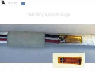
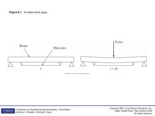
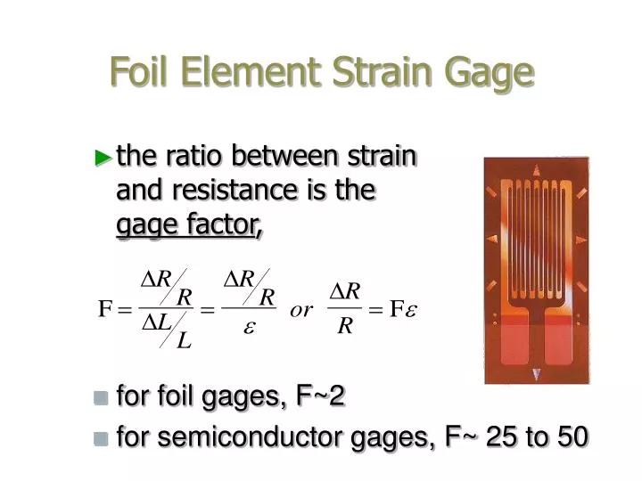
Foil Element Strain Gage. the ratio between strain and resistance is the gage factor ,. for foil gages, F~2 for semiconductor gages, F~ 25 to 50. +. V 2. _. “Quarter” Bridge Circuit. 1 of 4 “legs” of the Wheatstone Bridge is a strain gage. +. R gage. R A. V in. _. +. V out. +.

E N D
Foil Element Strain Gage • the ratio between strain and resistance is the gage factor, • for foil gages, F~2 • for semiconductor gages, F~ 25 to 50
+ V2 _ “Quarter” Bridge Circuit 1 of 4 “legs” of the Wheatstone Bridge is a strain gage + Rgage RA Vin _ + Vout + V1 RC RB _ _
+ V2 _ “Half” Bridge Circuit 2 of 4 “legs” of the Wheatstone Bridge are strain gages + R R+DR Vin _ + Vout + V1 R R-DR _ _
+ V2 _ “Full” Bridge Circuit All 4 “legs” of the Wheatstone Bridge are strain gages + R+DR R-DR Vin _ + Vout + V1 _ _ R-DR R+DR
+ V2 _ Half Bridge Circuit Two “legs” of the Wheatstone Bridge are strain gageswith same strain, R+DR + R+DR R Vin _ + Vout + V1 _ _ R R+DR
+ R-DR R+DR Vin R-DR R+DR - Load Cell w/Differential Amplifier RED Rf Ri - Vin GREEN WHITE + Ri V0 Rf BLACK