Download
1 / 49
570 likes | 834 Vues
TransCAD. Vehicle Routing. Introduction. The starting points for each route ( such as the warehouse) are known as depots , and the points to be visited are known as stops . A vehicle route starts at a depot, visits one or more stops, and may or may not return to the depot.

E N D
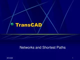
TransCAD Vehicle Routing
Introduction • The starting points for each route ( such as the warehouse) are known as depots, and the points to be visited are known as stops. A vehicle route starts at a depot, visits one or more stops, and may or may not return to the depot. • The goal of the procedure is to obtain a set of routes that minimizes the total time or distance traveled by the entire fleet of vehicles. The travel times or distances are stored in the vehicle routing matrix.
Factors • There are many factors that can make a vehicle routing problem more complex. The list below shows some common situations that are easily handled by TransCAD: • There are more than one warehouse location, and stores can be serviced by trucks from any one of these warehouses. This kind of a problem is known as a multiple-depot problem.
Factors • There are time restrictions on when deliveries can be make to some or all of the stores. This type of restriction is known as a time window. • There are time restrictions at the warehouse. This type of restriction is also known as a time window. • Each stop requires a certain amount of time to service. In most cases, each stop has a fixed service time that is independent of demand.
Factors • There is a time restriction on total route length, or route duration. For example, when delivering take-out food, it may be desirable that the full route length is not more than an hour. • There are backhaul stops. For example, vehicles may need to pick up empty containers at the end of their delivery trip. Backhaul stops can only be visited after all delivery stops are visited in a route.
Factors • A vehicle route may contain mixed pickup and delivery stops, where the pickups and deliveries do not need to correspond to each other. A stop may require either a pickup, a delivery, or both services. • A route does not need to end at the depot. In other words, the route does not contain the return trip from the last stop to the depot. This is often referred as an open-ended route instead of a closed tour. For example, a driver may want to drive home directly from the last stop of the day instead of returning to the depot. Another example is when the route duration constraint is effective only to the point of the last stop, such as in fresh goods delivery services.
Problem Examples • Determining assignments and routes for bridge inspectors • Managing a messenger or pizza-delivery service • Scheduling and routing sales personnel to potential customer sites • Delivering fuel oil to businesses or households, or gasoline to filling stations • Collecting solid waste from dump sites located at office or industrial complexes
Problem Examples • The TransCAD vehicle routing procedures use general-purpose methods that are appropriate for a fairly broad class of problems. There are some variations of the vehicle routing problem not handled directly within the TransCAD interface. • Mixed products – Several different products must be delivered in the same vehicle, but some vehicles have restrictions on the goods that can be carried • Partially pre-ordered routes – Certain stops must be visited in an exact order • Other constraints – There are work rules or regulations that impose other types of constraints on the routes to be developed
Vehicle Routing Procedure • There are six steps to solving a vehicle routing problem: • Preparing the depot and stop data • Use TransCAD to create geographic files that show the location of each depot and stop, along with information on the demand and other characteristics of each one. This step must be done before any of the others. • Creating the vehicle routing matrix • Create either a network-based or a straight line-based matrix file that contains the distance and travel time between each depot and stop.
Creating the vehicle table • Create a vehicle table that contains the required vehicle information. • Solving the vehicle routing problem • Run the routing procedure to develop efficient vehicle routes, summary reports, and itineraries. You may wish to do this several times with various settings and then compare the results of the different scenarios. • Displaying the vehicle routes • If you solved the routing problem with a network-based routing matrix, create a route system that lets you see the routes on a map. • Editing the vehicle routes • Once you have created a route, you can use the Vehicle Route Editing Toolbox to manually edit the routes.
Depot Layer Fields • The depot layer must have the following fields:
If you are using a network-based vehicle routing matrix you must also include the following field in the stop layer:
Stop Layer Fields • The stop layer must have the following fields:
If you are using a network-based vehicle routing matrix you must also include the following field in the stop layer:
Depending upon the operational characteristics you require for routing, the following additional fields may also be necessary:
Time Windows • In both the depot and the stop layers, the Open Time and Close Time fields use military format, so 8:30AM should be written as 830, while 6:30PM should be written as 1830. Times beyond midnight are written as numbers over 2400; for example, 12:30AM should be written as 2430. • If you do not need time window restrictions, you can simply set the open time to 0 and the close time to a large number (e.g., >2400).
Depot Assignments • If you are routing from multiple depots, you can either let the vehicle routing procedures assign each stop to a depot, or you can pre-assign any number of stops to specific depots. To pre-assign stops to depots, the stop layer must have a field containing the ID numbers of the depots to which each stop is assigned. Any stop that is not assigned in advance will be assigned to the nearest depot by the vehicle routing procedure. If a depot has excessive demand over its total vehicle capacity, some stops may be assigned to the second nearest depot.
Creating the Vehicle Routing Matrix • The vehicle routing matrix is a matrix file that contains the distance and travel time between each depot and stop and between every pair of stops. The vehicle routing matrix file is a primary input to the vehicle routing procedure. You can create a routing matrix from within the Vehicle Routing with Time Windows dialog box. • You can choose to compute distances and travel times in two different ways: • Use a line layer and network • Use straight-line connections between points
Using a Network to Create the Vehicle Routing Matrix • The network method is more accurate and lets you create a route system with the routing results. When you use a network to create a routing matrix, TransCAD computes the time and distance between each pair of stops, and between each depot and stop, by computing the shortest path between them. • Since the depots and stops may not be directly on the network, the routing matrix procedure performs the actual computation between the nodes nearest to each depot and stop.
Using a Network to Create the Vehicle Routing Matrix • To use this method, you must: • Have a network that contains both distance and travel time information for each segment • Tag each stop and depot with the ID of the nearest node • The network file must contain travel time in minutes. To tag stops and depots with the ID of the nearest network node, use the Edit-Fill command with the Tag option.
Using Straight-Line Connections to Create the Vehicle Routing Matrix • The straight-line method is a convenient approximation when you do not have a line layer. • When you use straight-line connections to create the routing matrix, TransCAD computes the distances between points based on the straight-line distance plus a circuity factor of 1.3. If you prefer to use a circuity factor other than 1.3, use the Matrix-Fill command on the completed routing matrix to scale the values by any desired factor.
Using Straight-Line Connections to Create the Vehicle Routing Matrix • This method does not require the preparation of a network, nor does it require depots and stops to be tagged with the ID of the nearest network node. • However, the distances and times that are estimated using this method are less accurate. In addition, you cannot display routes created from a straight line-based routing matrix without a line layer.
An Example Make sure the Boston.net is active.
Creating the Vehicle Table • To solve a vehicle routing problem with time windows, you will also need to prepare a vehicle table. This table contains specific about the fleet of vehicles available at a depot.
To Create a Vehicle Table Prepare the depot and stop data first.
To Solve the Vehicle Routing Problem with Time Windows VRPTW.WRK
Displaying Vehicle Routes • To Create a route system showing the vehicle routes, you must provide the following information: • The route table that was produced by the vehicle routing procedure • The line layer, network, and settings that were used to create the routing matrix • You can also display routes with a point layer, by creating desire lines that give a straight line representation of the routes.
Editing Vehicle Routes • Once you have created vehicle routes, you can use the Vehicle Route Editing toolbox to modify one or more routes. In addition, you can add any unassigned stops to routes. • Sometimes there will be stops that were not assigned to any route in the initial solution, or that are removed from routes by you. There stops are referred to as orphans.
To Open the Vehicle Route Editing Toolbox • To use the Vehicle Route Editing toolbox, you must have the following files open: • A map that contains the depots, stops, and the route system of the vehicle routes • The vehicle routing matrix used to create the routes
Displaying Routes with a Point Layer(Optional) • Normally you need a line layer to display routes. However, TransCAD allows you to create a line layer from a point layer, provided that your stops and depot(s) are on the same point layer. • Before creating the vehicle routing matrix, you should do the following steps: • Create a distance matrix: this matrix must have all stops and depot(s) you needed in both its rows and columns. • Create a desire line layer: the desire line layer is for displaying routes later. • Prepare additional input data: you will need to add a time field in the new desire lines layer, tag the Node ID field in your point layer, and create a network from the desire line layer.