Download
1 / 24
240 likes | 323 Vues
DAQ System to Search for GRBs using Water Cerenkov Detectors. Mario Castillo*, Gonzalo Perez*, Humberto Salazar* and L. Villaseñor ** * Facultad de Ciencias FisicoMatematicas, BUAP, Puebla ** Institute of Physics and Mathematics, University of Michoacan, Morelia. VII SILAFAE CAB

E N D
DAQ System to Search for GRBs using Water Cerenkov Detectors Mario Castillo*, Gonzalo Perez*, Humberto Salazar* and L. Villaseñor ** * Facultad de Ciencias FisicoMatematicas, BUAP, Puebla ** Institute of Physics and Mathematics, University of Michoacan, Morelia VII SILAFAE CAB Bariloche, Ar January, 13-21, 2009
4m2 x 1.4 m Single 5” EMI flat PMT Tyvek Ultra pure (~20 microS) water
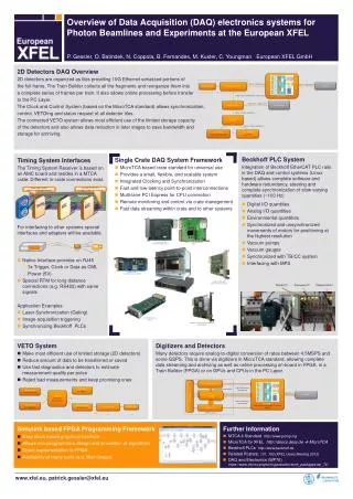
Schematic of the DAQ Board (one channel upgradable to 3 channels) Languages: VHDL + Perl & AWK 50 Mhz Clock JTAG PROM FPGA Xilinx Spartan 2E Antenna RS232 115200 Baud 4 operation modes: Trace, Charge, Rate, Muon Decay 1 PPS VP or UT Oncore GPS Receiver 50 ns 2x-4x clock Serial 9600 Baud RAM 10 bit ADC board 100-200 MHz|| Signal from PMT
ADC daugther boards 1 or 2 AD9214BRSZ-105 chips operating at 100MSPS.
We use one (two) delay-locked loop (DLL) circuits to obtain 100 (200) Mhz out of 50 MHz
Use a Motorola Oncore GPS receiver in precise Timing Mode model UT+ Position-Hold option 1PPS Cable and antenna Delay Time RAIM option to isolate satellites with erroneous time measurements
Trace mode, samples 30 trace points every 10 ns in real time and measures charge, amplitude, baseline and STD
Trace Mode: Up to 180 full traces per second Bottle- neck: 115200 baud comm rate
Charge mode: Up to 2880 Charge & Amplitude measurements per second (1920 per s if rise time is also measured)
Measure Charge, Amplitude,T10-50,T10-90 with good precision for three different triggers. Arbitrary muons threshold of 30mV
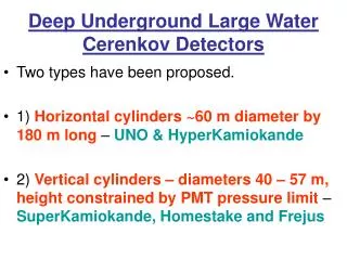
1.54 m diameter, 1.2 m water, one 8” PMT, tyvek 1/5 in volume of an Auger WCD
LabView based DAS
Rise time behaves similarly to Charge over amplitude
Charge spectrum 2000 masl 4550 masl
Muon decay mode: Time between consecutive pulses in a 20 microsec window and time over threshold with granularity of 5 ns
Stopping muon at 0.1 VEM Decay electron at 0.17 VEM Crossing muon at 1.05 VEM Alarcón M. et al., NIM A 420 [1-2], 39-47 (1999).
Conclusions DAQ system prototype tested 1-3 ADC channels at 100-200 MHz Precise timing from GPS 4 operation modes: Trace, charge, muon decay and rate To do: implement as a single board