Download
1 / 84
840 likes | 847 Vues
2.10 Under what conditions are mixed cells a problem in raster data models? In what ways may the problem of mixed cells be addressed?. 2.18. 2.21 Why do we need to compress data? Which is most commonly compressed, raster data or vector data? Why?. 2.24. Geodesy & Map Projections.

E N D
2.10 Under what conditions are mixed cells a problem in raster data models? In what ways may the problem of mixed cells be addressed? Lecture 3
2.18 Lecture 3
2.21 Why do we need to compress data? Which is most commonly compressed, raster data or vector data? Why? Lecture 3
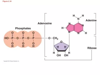
2.24 Lecture 3
Geodesy & Map Projections Chapter 3 Lecture 3
Introduction • To effectively use GIS, it is important to understand: • How coordinate systems are established for the surface of the Earth. • How coordinates are measures on the Earth’s curved surface. • How these coordinates are converted for use on flat maps • To understand these things we need some knowledge of geodesy and map projections. Lecture 3
Geodesy • Geodesy is the science of measuring the size and shape of the earth. • All measurements are relative to some reference, and the best estimates of this reference have changed over time. • Maps use a two dimensional reference system, but this doesn’t work well for long distances or over the whole Earth. Lecture 3
Defining a Spatial Referencing System • Every spatial feature needs to be referenced to a location for GIS use • Spatial reference systems provide a framework to define positions on the Earth‘s surface. • Steps • Define the size and shape of the Earth. • Establish a datum – reference surface from which other points can be measured. • Develop a spatial reference system: • Origin • Orientation of the axes • Units of measure Lecture 3
Difficulty in Defining Coordinates for the Earth • Three complicating factors: • A flat map must distort geometry in some way. • The irregular shape of the Earth. • The imperfections of our measurements. • Because of these three factors we may have several sets of coordinates for the same location. Lecture 3
Early Measurements The Earth as a Sphere Lecture 3
Defining the Ellipsoid • Newton reasoned that the Earth was not a sphere. • Efforts were then focused on measuring the size of the ellipsoid. Lecture 3
Local or Regional Ellipsoid Origin, r1, and r2 of ellipsoid specified such that separation between ellipsoid and Geoid is small These ellipsoids have names, e.g., Clarke 1880, or Bessel Lecture 3
The Earth is NOT an Ellipsoid (only very close in shape) The Earth has irregularities in it - deviations from a perfectly ellipsoidal shape These deviations are due to differences in the gravitational pull of the Earth Deviations are NOT the surface topography Lecture 3
The Earth’s True Shape is Best Described as a GEOID Lecture 3
The Geoid is a measured surface (not mathematically defined) Found via surface instruments (gravimeters) towed behind boats, planes, or carried in vehicles. Or, from measurements of satellite paths (ephemerides) May be thought of as an approximation of mean sea level Lecture 3
Measuring Elevations (Dynamic Height) Lecture 3
Datum • A set of points on Earth for which the horizontal and vertical positions have been accurately measured. • These form a mathematical surface from which all other points can be measured. • Many countries have government bodies charged with making these measurements; e.g. National Geodetic Survey Lecture 3
http://www.ngs.noaa.gov/datasheets/ Lecture 3
Data Sheet Lecture 3
Defining a Datum Horizontal Datum Specify the ellipsoid Specify the coordinate locations of features on this ellipsoidal surface Vertical Datum Specify the ellipsoid Specify the Geoid – which set of measurements will you use, or which model Lecture 3
Two Main Eras of Datums There are two horizontal control networks commonly referred to North American Datum of 1927 (also NAD27) North American Datum of 1983 (also NAD83), to replace NAD27 Lecture 3
NAD27 vs NAD83 Kansas Lecture 3
Datum “Adjustment” A datum adjustment is a calculation of the coordinates of each benchmark – this is how we specify the “reference surface” Not straightforward, because of contradictions Errors in distance, angle measurements Improvements in our measurements of Geoid, best spheroid Improvements in computing capabilities Lecture 3
Datum Versions • NAD83 (19860 • NAD83(HARN) – High Accuracy Reference Networks • NAD83(1996) • NAD83(2007) Lecture 3
Vertical Datums Like horizontal, but referenced to standard elevation and established using vertical leveling Two major vertical datums, North American Vertical Datum of 1927 (NAVD29), and an update, North American Vertical Datum of 1988 (NAVD88) Lecture 3
Global Ellipsoid Selected so that these have the best fit “globally”, to sets of measurements taken across the globe. Generally have less appealing names, e.g. WGS84, or ITRF 2000 Lecture 3
Datum Transformations • Converting coordinates from one datum to another requires a transformation. • Simple formulas do not exist for NAD27 to NAD83 conversions. Lecture 3
The Evolution of N. Am. Datums Lecture 3
Review • Geographic coordinates in decimal degrees: • Latitude is positive above the equator and negative below. • Longitude is positive east of the Greenwich meridian and negative west of the Greenwich meridian. • Two eras of North American datums: • NAD 27 and NAD 83. • Must transform from one to the other. Lecture 3
There are many different versions of the NAD83 datum. • These should not be combined unless you are certain that the errors will be small. • There are also vertical datums. • Elevations may be ellipsoidal or orthometric heights. Lecture 3
GIS Use and Datums • GIS projects should not mix datums unless you are sure that the datum shifts are small relative to the analysis. • Datum transformations are estimated relationships that are developed with a specific data sets. • All datum transformations will introduce error into the data set. Lecture 3
Map Projections Lecture 3
Map projections are used to transfer or “project” geographical coordinates onto a flat surface. . There are many projections/coordinate systems: Maine example: • NAD 27 Universal Transverse Mercator – Zone 19N • NAD 27 Maine State Plane (based on the TM projection) • East Zone • West Zone • NAD 83 Universal Transverse Mercator– Zone 19N • NAD 83 Maine State Plane (based on the TM projection) • East Zone • Central Zone • West Zone Lecture 3
Projections may be categorized by: • The location of projection source • The projection surface • Surface orientation • Distortion properties Lecture 3
Categorized by the Location of Projection Source Gnomonic - center of globe Stereographic - at the antipode Orthographic - at infinity Lecture 3 Source:http://www.fes.uwaterloo.ca/crs/geog165/mapproj.htm
The projection surface: Cone – Conic Cylinder - Cylindrical Plane - Azimuthul Lecture 3
The projection surface: Cone – Conic Cylinder - Cylindrical Plane - Azimuthul Lecture 3
Projection Surfaces – “developable” Lecture 3
The Tangent Case vs. The Secant Case In the tangent case the cone, cylinder or plane just touches the Earth along a single line or at a point. • In the secant case, the cone, or cylinder intersects or cuts through the Earth as two circles. • Whether tangent or secant, the location of this contact is important because it defines the line or point of least distortion on the map projection. • This line of true scale is called the standard parallel or standard line. Lecture 3
Standard Parallel • The line of latitude in a conic or cylindrical projection where the cone or cylinder touches the globe. • A tangent conic or cylindrical projection has one standard parallel. • A secant conic or cylindrical projection has two standard parallels. Lecture 3
The Orientation of the Surface Lecture 3
Projections Categorized by Orientation: Equatorial - intersecting equator Transverse - at right angle to equator Lecture 3
Specifying Projections • The type of developable surface (e.g., cone) • The size/shape of the Earth (ellipsoid, datum), and size of the surface • Where the surface intersects the ellipsoid • The location of the map projection origin on the surface, and the coordinate system units Lecture 3
Defining a Projection – LCC(Lambert Conformal Conic) • The LCC requires we specify an upper and lower parallel – 20o & 60o • An ellipsoid – GRS 1980 • A central meridian – 96o • A projection origin – Lat. 40o origin central meridian Lecture 3
Conformal Projections • Locally preserves angles/shape. • Any two lines on the map follow the same angles as the corresponding original lines on the Earth. • Projected graticule lines always cross at right angles. • Area, distance and azimuths change. Lecture 3