Download
1 / 1
10 likes | 129 Vues
Figure 2: Electric field of 2 standing wave (SW) solutions from 2 boundary conditions at the coupler end. Considering fields inside the coupler region, the traveling wave (TW) solution is obtained from the superposition of 2 SW solutions by the relationship;. (a). (b).

E N D
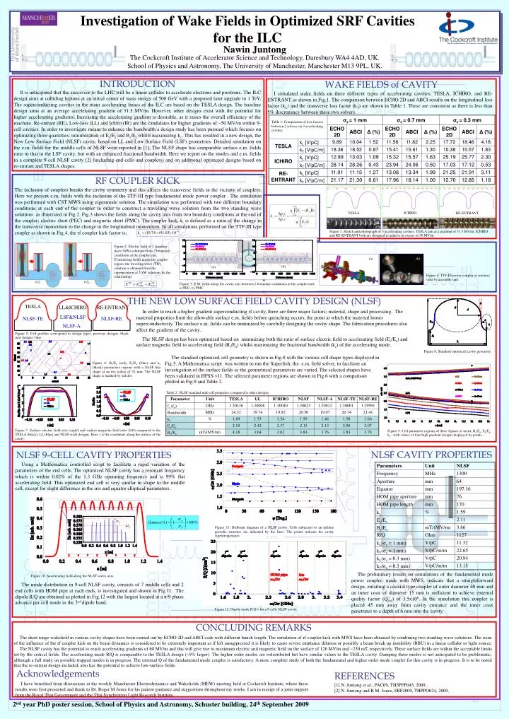
Figure 2: Electric field of 2 standing wave (SW) solutions from 2 boundary conditions at the coupler end. Considering fields inside the coupler region, the traveling wave (TW) solution is obtained from the superposition of 2 SW solutions by the relationship; (a) (b) Figure 4: TTF-III power coupler a) cutaway view b) assembly unit. Figure 3: E.M. fields along the cavity axis between 2 boundary conditions at the coupler end; a) PEC, b) PMC. (b) (a) Figure 10: Accelerating field along the NLSF cavity axis. ICHIRO TESLA RE-ENTRANT Figure 1: Sketch and photograph of 3 accelerating cavities. TESLA aim at a gradient of 31.5 MV/m, ICHIRO and RE-ENTRANT both are designed to achieve in excess of 50 MV/m. Figure 12: Dipole mode R/Q’s for a 9-cells NLSF cavity. Figure 11: Brillouin diagram of a NLSF cavity. Cells subjected to an infinite periodic structure are indicated by the lines. The points indicate the cavity eigenfrequencies. Investigation of Wake Fields in Optimized SRF Cavities for the ILC Nawin Juntong The Cockcroft Institute of Accelerator Science and Technology, Daresbury WA4 4AD, UK.School of Physics and Astronomy, The University of Manchester, Manchester M13 9PL, UK. INTRODUCTION WAKE FIELDS of CAVITY It is anticipated that the successor to the LHC will be a linear collider to accelerate electrons and positrons. The ILC design aims at colliding leptons at an initial center of mass energy of 500 GeV with a proposed later upgrade to 1 TeV. The superconducting cavities in the main accelerating linacs of the ILC are based on the TESLA design. The baseline design aims at an average accelerating gradient of 31.5 MV/m. However, other designs exist with the potential for higher accelerating gradients. Increasing the accelerating gradient is desirable, as it raises the overall efficiency of the machine. Re-entrant (RE), Low-loss (LL) and Ichiro (IR) are the candidates for higher gradients of ~50 MV/m within 9-cell cavities. In order to investigate means to enhance the bandwidth a design study has been pursued which focuses on optimizing three quantities: minimization of Es/Ea and Bs/Ea whilst maximizing kc. This has resulted in a new design, the New Low Surface Field (NLSF) cavity, based on LL and Low Surface Field (LSF) geometries. Detailed simulation on the e.m. fields for the middle cells of NLSF were reported in [1]. The NLSF shape has comparable surface e.m. fields ratio to that in the LSF cavity, but with an enhanced fractional bandwidth. Here we report on the modes and e.m. fields in a complete 9-cell NLSF cavity [2] (including end-cells and couplers) and on additional optimized designs based on re-entrant and TESLA shapes. I simulated wake fields on three different types of accelerating cavities; TESLA, ICHIRO, and RE-ENTRANT as shown in Fig.1. The comparison between ECHO 2D and ABCI results on the longitudinal loss factor (kL) and the transverse loss factor (kT) are shown in Table 1. These are consistent as there is less than 5% discrepancy between these two solvers. Table 1: Comparison of loss factors between 2 solvers on 3 accelerating cavities. RF COUPLER KICK The inclusion of couplers breaks the cavity symmetry and this affects the transverse fields in the vicinity of couplers. Here we present e.m. fields with the inclusion of the TTF-III type fundamental mode power coupler . The simulation was performed with CST MWS using eigenmode solution. The simulation was performed with two different boundary conditions at each end of the coupler in order to construct a travelling wave solution from the two standing wave solutions as illustrated in Fig.2. Fig.3 shows the fields along the cavity axis from two boundary conditions at the end of the coupler; electric short (PEC) and magnetic short (PMC). The coupler kick, k, is defined as a ratio ofthe change in the transverse momentum to the change in the longitudinal momentum. In all simulations performed on the TTF-III type coupler as shown in Fig.4, the rf coupler kick factor is; THE NEW LOW SURFACE FIELD CAVITY DESIGN (NLSF) TESLA LL&ICHIRO RE-ENTRANT In order to reach a higher gradient superconducting rf cavity, there are three major factors; material, shape and processing. The material properties limit the allowable surface e.m. fields before quenching occurs, the point at which the material looses superconductivity. The surface e.m. fields can be minimized by carefully designing the cavity shape. The fabrication procedures also affect the gradient of the cavity. The NLSF design has been optimized based on minimizing both the ratio of surface electric field to accelerating field (Es/Ea) and surface magnetic field to accelerating field (Bs/Ea) whilst maximizing the fractional bandwidth (kc) of the accelerating mode. LSF&NLSF NLSF-TE NLSF-RE NLSF-A Figure 5: Cell profiles correspond to design types, previous designs: black, new designs: blue. Figure 8: Standard optimized cavity geometry. The standard optimized cell geometry is shown in Fig.8 with the various cell shape types displayed in Fig.5. A Mathematica script was written to run the Superfish, the e.m. field solver, to facilitate an investigation of the surface fields as the geometrical parameters are varied. The selected shapes have been validated in HFSS v11. The selected parameter regions are shown in Fig.6 with a comparison plotted in Fig.9 and Table 2. Figure 6: Bs/Ea (red), Es/Ea (blue) and kc (black) parameters regions with a NLSF like shape at an iris radius of 32 mm. The NLSF shape is marked by red dot. Table 2: NLSF standard mid-cell properties compared to other designs. Figure 7: Surface electric field ratio (right) and surface magnetic field ratio (left) compared to the TESLA (black), LL (blue) and NLSF (red) designs. Here s is the coordinate along the surface of the cavity. Figure 9: Cell parameter regions of three figures of merit, Bs/Ea,Es/Ea, kc, with values of four high gradient designs displayed by points. NLSF CAVITY PROPERTIES NLSF 9-CELL CAVITY PROPERTIES Using a Mathematica controlled script to facilitate a rapid variation of the parameters of the end cells. The optimized NLSF cavity has a resonant frequency which is within 0.02% of the 1.3 GHz operating frequency and is 99% flat accelerating field. This optimized end cell is very similar in shape to the middle cell, except for slight difference in the iris and equator elliptical parameters. The preliminary results on simulations of the fundamental mode power coupler, made with MWS, indicate that a straightforward design, entailing a coaxial type coupler of outer diameter 40 mm and an inner coax of diameter 15 mm is sufficient to achieve external quality factor (Qext) of 3.5x10⁶. In the simulation this coupler is placed 45 mm away from cavity entrance and the inner coax penetrates to a depth of 6 mm into the cavity. The mode distribution in 9-cell NLSF cavity, consists of 7 middle cells and 2 end cells with HOM pipe at each ends, is investigated and shown in Fig.11. The dipole R/Q are obtained as plotted in Fig.12 with the largest located at a π/9 phase advance per cell mode in the 3rd dipole band. CONCLUDING REMARKS The short range wakefield in various cavity shapes have been carried out by ECHO 2D and ABCI code with different bunch length. The simulation of rf coupler kick with MWS have been obtained by combining two standing wave solutions. The issue of the influence of the rf coupler kick on the beam dynamics is considered to be extremely important as if left unsuppressed it is likely to cause severe emittance dilution or possibly a beam break up instability (BBU) in a linear collider or light source. The NLSF cavity has the potential to reach accelerating gradients of 60 MV/m and this will give rise to maximum electric and magnetic field on the surface of 126 MV/m and ~230 mT, respectively. These surface fields are within the acceptable limits set by the critical fields. The accelerating mode R/Q is comparable to the TESLA design (~9% larger). The higher order modes are redistributed but have similar values to the TESLA cavity. Damping these modes is not anticipated to be problematic; although a full study on possible trapped modes is in progress. The external Q of the fundamental mode coupler is satisfactory. A more complete study of both the fundamental and higher order mode coupler for this cavity is in progress. It is to be noted that the re-entrant design included, also has the potential to achieve low-surface fields. Acknowledgements REFERENCES I have benefited from discussions at the weekly Manchester Electrodynamics and Wakefields (MEW) meeting held at Cockcroft Institute, where these results were first presented and thank to Dr. Roger M Jones for his patient guidance and suggestions throughout my works. I am in receipt of a joint support from the Royal Thai Government and the Thai Synchrotron Light Research Institute. [1] N. Juntong et al., PAC09, TH5PFP045, 2009., [2] N. Juntong and R.M. Jones, SRF2009, THPPO024, 2009. 2nd year PhD poster session, School of Physics and Astronomy, Schuster building, 24th September 2009