Download
1 / 12
120 likes | 215 Vues
Ch. 2. Specification and Modeling. 2.1 Requirements Describe requirements and approaches for specifying and modeling embedded systems. Specification for embedded systems provide models of the system under design.

E N D
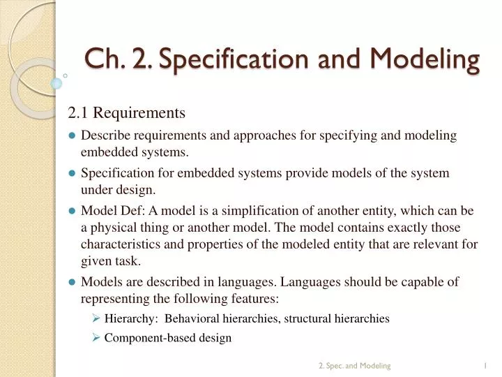
Ch. 2. Specification and Modeling 2.1 Requirements Describe requirements and approaches for specifying and modeling embedded systems. Specification for embedded systems provide models of the system under design. Model Def: A model is a simplification of another entity, which can be a physical thing or another model. The model contains exactly those characteristics and properties of the modeled entity that are relevant for given task. Models are described in languages. Languages should be capable of representing the following features: Hierarchy: Behavioral hierarchies, structural hierarchies Component-based design 2. Spec. and Modeling
Concurrency • Synchronization and communication • Timing-behavior • Modeling time must be possible in the following four contexts: • Techniques for measuring elapsed time • Means for delaying of processes for a specified • Possibility of specify timeouts • Methods for specifying deadlines and schedules • State-oriented behavior • Event-handling • Exception-oriented behavior • Presence of programming elements • Executability • Support for the design of large systems. • Domain-specific support • Readability • Portability and flexibility • Termination • Support for non-standard I/O-devices • Non-functional properties • Support for design of dependable systems 2. Spec. and Modeling
No obstacles to the generation of efficient implementations • Appropriate model of computation (MoC) 2.2 Model of computation • MoCs describe the mechanism assumed for performing computation. • Components and the organization of computations in such components: Procedure, processes, functions, finite state machines and possible components. • Communication protocols: These protocols describe methods for communication between components. Asynchronous message passing and rendez-vous based communication are examples of communication protocols. • Relations between components can be captured in graphs. • Dependence graphs T2 T5 T1 T3 T4 2. Spec. and Modeling
Task graphs may contain more information than modeled in dependence graph. Task graphs may include the following extensions of dependence graphs: • Timing information: Tasks may have arrived times, deadlines, periods, and execution times. • Graphs including timing information • Distinction between different types of relations between computations • In Fig. 2.4, partially filled circles identify I/O edges. • Exclusive access to resource • Periodic scheduled (0, 7] (1, 8] (3, 10] T1 T2 T3 T2 T5 T1 T3 T4 2. Spec. and Modeling
Hierarchical graph nodes • At a higher hierarchical level, the nodes may denote complex tasks, at a lower level basic blocks and even at an even lower individual arithmetic operations. • Models of communication • Shared memory • Message passing • Asynchronous message passing • Synchronous message passing • Extended rendez-vous, remote invocation (RMI, remote method invocation) • Organization of computation within components • Von-Neumann model • Discrete event model • Finite state machines • Differential equations T2 T5 T1 T3 T4 2. Spec. and Modeling
Combined models • StateCharts = finite state machine + shared memory • SDL = finite state machine + asynchronous message passing • ADA, CSP = von-Neumann execution + synchronous message passing 2.3 Early design phases 2.3.1 Use case • Use cases describe possible applications of the SUD. • Support for a systematic approach to early specification phases in the goal of the so-called UML (Unified Modeling Language) standardization effort. • UML primarily aims at the support of the software design process. UML provides a standardized form for use cases. • Use case identify different classes of users as well as the application to be supported by the SUD. • Use case in neither a precisely specified model of the computations nor is there a precisely specified model of the computation. • Use case example for answering machine 2. Spec. and Modeling
Introduction to UML 2.3.2 Message Sequence Charts • SCs describe partial orders between message transmissions. SCs display a possible behavior of a SUD. • The use cases of the answering machine as an example. (p. 37) • Complex control-dependent actions cannot be described by SCs. 2. Spec. and Modeling
Time/distance diagrams 2.4 Communicating finite state machines (CFSMs) 2.4.1 Timed automata • Timed automata are essentially automata extended with real-valued variables. • Servicing in incoming line in an answering machine • Definition: A timed automaton is a tuple (S, s0, E, I) where: • S is a finite set of states. • s0 is the initial state. • ESB(C)2CS is the set of edges. • B(C) models the conjunctive condition which must hold. • 2C reflects the set of clock variables which are reset whenever the transit takes place. • I: SB(C) is the set of invariants for each of the states. 2.4.2 StateCharts: implicit shared memory communication 2.4.2.1 Modeling of hierarchy • The StateCharts language describes extended FSMs. • The key extension is hierarchy. 2. Spec. and Modeling
Hierarchy is introduced by means of super-states. • Definitions: • States comprising other states are called super-states. • States included in super-states are called sub-state of the super-states. • Hierarchical state diagram (Fig. 2.14) • State diagram using the default state mechanism (Fig. 2.15) • History mechanism is possible to return to the last sub-state that was active before a super-state was left. • State diagram using the history and the default state mechanism. • Specification techniques must also be able to describe concurrency conveniently. Towards this end, the StateCharts language provides a second class of super states, so called AND-states. • Definition: Super-states S are called AND-super-states if the system containing S will be in all of the sub-states of S whenever it is in S. • Answering machine (Fig. 2.18) • Answering machine with modified on/off switch processing (Fig. 2.19) 2.4.2.2 Timer • Serving the incoming line in Lproc (Fig. 2.21) 2. Spec. and Modeling
2.4.2.2 Edge labels and StateMate semantics • The general form of an edge label is “event[condition]/reaction”. All three label parts are optional. • Possible reactions include the generation of events and assignments to variables. • The condition-part implies a test of the values of variables or a test of the current state of the system. • The event-part refers to a test of current events. • Examples • on-key / on:=1 • [on=1] • off-key [not in Lproc] / on:=0 2.4.3 Synchronous language 2.4.3.1 Motivation 2.4.3.2 Examples of synchronous languages: Esteral, Lustre and SCADE • Esteral is a reactive language: when activated with an input event, Esteral models react by producing an output event. • Esteral is a synchronous language: all reactions are assumed to be completed in zero time and it is sufficient to analyze the behavior at discrete moments in time. 2. Spec. and Modeling
2.4.4 SDL: A case of message passing 2.4.4.1 Feature of the language • SDL wasdesigned for distributed application. • SDL pleases both types of users since it provides textual as well as graphical format. • Processes are the basic elements of S이. Processesrepresent components modeled as extended finite state machines. Extensions include operations on data. • Symbols used in the graphical form of SDL. • FSM to be described in SDL SDL-representation (Fig. 2.27, Fig 2.28) identifies initial state state Input output 2. Spec. and Modeling