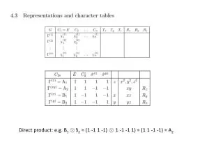
Download
1 / 45
450 likes | 583 Vues
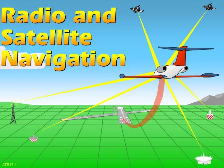
ATB17-1. OBJECTIVES. On an End-of-Lesson Test, and in accordance with the Aeronautical Information Manual (AIM), AC 61-23,The Pilot’s Handbook, and AC 61-27, Instrument Flying Handbook, you will identify the characteristics of: 1. Radio and Satellite Navigation. 2. Federal Airway System.

E N D
OBJECTIVES • On an End-of-Lesson Test, and in accordance with the Aeronautical Information Manual (AIM), AC 61-23,The Pilot’s Handbook, and AC 61-27, Instrument Flying Handbook, you will identify the characteristics of: • 1. Radio and Satellite Navigation. • 2. Federal Airway System. ATB17-2
VHF OMNI-DIRECTIONAL RANGE (VOR) MAGNETIC NORTH 0° 270° WEST 090° EAST 180° SOUTH ATB17-3
LINE-OF-SIGHT VHF-UHF OMNI-DIRECTIONAL FACILITIES (VOR) VHF TACAN (UHF) VORTAC (VHF/UHF) ARE ALL LINE-OF-SIGHT. ATB17-4
RANGE AND CLASSIFICATION CLASS T L H H H H DISTANCE AND ALTITUDES 12,000’ and below Below 18,000’ Below 18,000’ Within the conterminous 48 States only, between 14,500 and 17,999 18,000’ - FL 450 Above FL 450 (MILES) 25 40 40 100 130 100 ATB17-5
VOR IDENTIFICATION “TULSA V-O-R” ALTERNATING VOICE AND MORSE CODE ATB17-6
RESPONSE ITEM A VOR antenna transmission pattern is A. omni-directional. B. nondirectional. C. fan-shaped. A. omni-directional. A. omni-directional. A. omni-directional. ATB17-7
RESPONSE ITEM A VOR station projects A. 360 usable true radials. B. 360 usable magnetic radials. C. an infinite number of bearings. B. 360 usable magnetic radials. B. 360 usable magnetic radials. B. 360 usable magnetic radials. ATB17-8
RESPONSE ITEM The different classes of VORs are A. High, Low, Terminal. B. High, Medium, Low. C. High, Low, Compass Locator. A. High, Low, Terminal. A. High, Low, Terminal. A. High, Low, Terminal. ATB17-9
TACAN DISTANCE (DME) AZIMUTH (BEARING) AN ULTRA-HIGH FREQUENCY NAVIGATION AID WHICH PROVIDES SUITABLY EQUIPPED AIRCRAFT A CONTINUOUS INDICATION OF BEARING AND DISTANCE TO THE TACAN STATION. ATB17-10
DME (DISTANCE MEASURING EQUIPMENT) PULSE CODED REPLY AIRBORNE INTERROGATOR PULSE CODED INTERROGATION SLANT RANGE GROUND-BASED TRANSPONDER ATB17-11
RESPONSE ITEM A TACAN station projects A. 360 usable true radials. B. 360 usable magnetic radials. C. an infinite number of bearings. B. 360 usable magnetic radials. B. 360 usable magnetic radials. B. 360 usable magnetic radials. ATB17-12
RESPONSE ITEM TACAN frequencies are in the ______ band. A. L/MF B. VHF C. UHF C. UHF C. UHF C. UHF ATB17-13
VORTAC ATB17-14
RESPONSE ITEM DME distance is displayed A. as slant range distance. B. as horizontal distance. C. in time to station. A. as slant range distance. A. as slant range distance. A. as slant range distance. ATB17-15
RESPONSE ITEM What DME equipment on the ground is required to respond to the aircraft interrogator? A. Transmitter B. Transponder C. VOR B. Transponder B. Transponder B. Transponder ATB17-16
WAYPOINTS 0 9 27 TUL 18 TUL 211/30 ATB17-17
WAYPOINTS 2 1 1 RADIAL 3 0 DISTANCE ATB17-18
NONDIRECTIONAL RADIO BEACON USED IN: AIRBORNE RADIO DIRECTION FINDING INSTRUMENT APPROACHES HOLDING NDB ATB17-20
18 9 0 27 DIRECTION FINDING ATB17-21
RESPONSE ITEM How are all NDBs, except compass locators, identified? A. Three-letter identifier in Morse code B. Two-letter identifier in Morse code C. Aural tone A. Three-letter identifier in Morse code A. Three-letter identifier in Morse code A. Three-letter identifier in Morse code ATB17-22
ILS TRANSMITTERS LOCALIZER ANTENNA MIDDLE MARKER OUTER MARKER GLIDE SLOPE ANTENNA ATB17-23
LOCALIZER NORMAL LIMITS OF LOCALIZER COVERAGE. THE SAME AREA APPLIES TO A BACK COURSE WHEN PROVIDED. 35° 10° 10 NM 18 NM LOCALIZER ANTENNA 10° 35° ATB17-24
MARKER BEACON MARKER OM MM IM BC CODE LIGHT BLUE AMBER WHITE WHITE ATB17-25
GLIDE SLOPE/GLIDE PATH GLIDE SLOPE GLIDE PATH ATB17-26
DISTANCE MEASURING EQUIPMENT (DME) Arc 2700 DME 15 R-055 LOCALIZER 111.9 I-URN (IAF) 1292 (IAF) R-055 LOM BURLINGTON 321 UR 954 2400 NoPT MM 1258 2800 271° 091° LOM 046° 226° FLORENCE 287 CV CINCINNATI 117.3 CVG Chan 120 FACILITIES 2400 ENROUTE 035° R-140 15 2500 DME 2300 Arc ATB17-27
RESPONSE ITEM An ILS approach becomes a nonprecision approach when the _______ fails. A. localizer B. localizer and glide slope C. glide slope C. glide slope C. glide slope C. glide slope ATB17-28
RESPONSE ITEM Which of the following components of an ILS is designed to provide the pilot with directional azimuth guidance to the runway? A. Markers B. Glide Path C. Localizer C. Localizer C. Localizer C. Localizer - This informs the pilot to turn right or left in order to remain on course. ATB17-29
RESPONSE ITEM The purpose of a marker beacon is to A. provide directional information. B. identify a particular location. C. provide airborne radio direction finding. B. identify a particular location. B. identify a particular location. B. identify a particular location. ATB17-30
MLS APPROACH CAT I DECISION HEIGHT CAT II DECISION HEIGHT CENTERLINE APPROACH ATB17-31
MLS PROVIDES MULTIPLE APPROACH PATHS ATB17-32
RESPONSE ITEM MLS identification is a four-letter designation starting with the letter A. I. B. M. C. N Beacon. B. M. B. M. B. M. ATB17-33
GLOBAL POSITIONING SYSTEM (GPS) ATB17-34
GPS NAVIGATION GPS Satellites ATB17-35
V22 AIRWAY SYSTEM NAVAID VICTOR AIRWAY V187 V74 V293 V10 V35 INTERSECTION ATB17-36
ACCURACY, PRECISION AND SAFETY: AIR TRAFFIC CONTROL AND GPS VIDEO CLIP
AIRWAYS NAVAID NAVAID 65 65 51 NM 51 NM CHANGEOVER POINT ATB17-37
AIRWAYS NAVAID NAVAID 51 79 CHANGEOVER POINT 51 NM 51 NM ATB17-38
AIRWAYS INTERSECTION NAVAID 79 51 NM ATB17-39
SHARED ROUTE V74-235 TWO AIRWAYS SHARING THE SAME ROUTE V293-41 V22 ATB17-40
JET ROUTE SYSTEM INTERSECTION J25-87 NAVAID J24 J102 J213 J110 JET ROUTE J37 NAVAID ATB17-41
RESPONSE ITEM What is the upper limit of a low altitude VOR? A. Up to and including 18,000 feet MSL B. Up to, but NOT including 18,000 feet MSL C. Up to, but NOT including 18,000 feet AGL B. Up to, but NOT including 18,000 feet MSL B. Up to, but NOT including 18,000 feet MSL B. Up to, but NOT including 18,000 feet MSL ATB17-42
RESPONSE ITEM The base of the Jet Route structure begins with flight level A. 160. B. 180. C. 450. B. 180. B. 180. B. 180. ATB17-43