Download
1 / 35
350 likes | 477 Vues
Schedule…. Memory & Counters. Exodus 12:14 14 And this day shall be unto you for a memorial ; and ye shall keep it a feast to the LORD throughout your generations; ye shall keep it a feast by an ordinance for ever. D&C 107:100

E N D
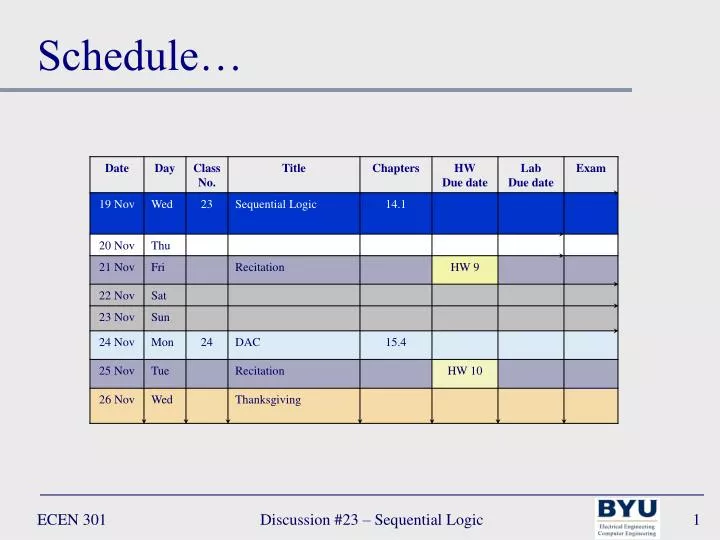
Schedule… Discussion #23 – Sequential Logic
Memory & Counters Exodus 12:14 14 And this day shall be unto you for a memorial; and ye shall keep it a feast to the LORD throughout your generations; ye shall keep it a feast by an ordinance for ever. D&C 107:100 100 He that is slothful shall not be counted worthy to stand, and he that learns not his duty and shows himself not approved shall not be counted worthy to stand. Even so. Amen. Discussion #23 – Sequential Logic
Lecture 23 – Combinational & Sequential Logic Discussion #23 – Sequential Logic
2To4 Intel D FA n Mem m m Digital Logic Hierarchy Combinational Transistors Gates Processors Sequential Discussion #23 – Sequential Logic
Combinational Logic Decoders Multiplexers Discussion #23 – Sequential Logic
2-to-4 Decoder W X Y Z A B DECODERSymbol Decoders • Decode the input and signify its value by raising just one of its outputs. • A decoder with n inputs has 2n outputs W X Y Z Discussion #23 – Sequential Logic
Decoders • Write the truth table W X Y Z Discussion #23 – Sequential Logic
Decoders • Write the truth table W X Y Z Discussion #23 – Sequential Logic
A B 1 0 S C MULTIPLEXOR Symbol Multiplexors • Connect one of its inputs to its output according to select signals • Useful for selecting one from a collection of data inputs. • Usually has 2n inputs and n select lines. Discussion #23 – Sequential Logic
A B 1 0 S C MULTIPLEXOR Symbol Multiplexors • Write the truth table Discussion #23 – Sequential Logic
A B 1 0 S C MULTIPLEXOR Symbol Multiplexors • Write the truth table Discussion #23 – Sequential Logic
Sequential Logic Discussion #23 – Sequential Logic
D S Q Q T Q D Q R E CLK CLK S J Q Q E CLK R K Latches and Flip-Flops (FFs) Latch/FF: basic building block of memory devices • Bistable devices – remain in one of 2 states (logic 0 or logic 1) • Has 2 outputs (one is the complement of the other) – often only one is shown (the other is implied) Latches – imply that not controlled by a clock FFs – imply that they are controlled by a clock D - FF T - FF SR – Latch D – Latch with enable SR – Latch with enable JK - FF Discussion #23 – Sequential Logic
S Q R SR Latch SR Latch has 3 allowed states: • Set (set Q to 1): S = 1, R = 0 • Reset (reset Q to 0): R = 1, S = 0 • Present state (keep Q as is): S = 0, R = 0 SR Latch has 1 illegal state: • Instability (causes Q to switch between 0 and 1): S = 1, R = 1 Present state S Q Reset Set Q R Illegal Discussion #23 – Sequential Logic
SR Latch Timing diagram: a graph of inputs and outputs over time. FF is again reset FF is set FF is set FF is reset HOLD HOLD Q HOLD HOLD R S Time Discussion #23 – Sequential Logic
CLR S Q E Q R PRE CLR PRE R S E SR Latch SR Latch with additional inputs: • Enable (E) – S and R can only change Q when E is 1 • Preset (PRE) – regardless of S, R, or E, put Q to 1 when PRE is 1 • Clear (CLR) – regardless of S, R, E, or PRE, put Q to 0 when CLR is 1 • Precedence: • If CLR = 1, Q = 0 • If PRE = 1, Q = 1 • If E = 1, Q is set based on SR • If S = 0 and R = 0, Q = hold • If S = 0 and R = 1, Q = 0 • If S = 1 and R = 0, Q = 1 • If S = 1 and R = 1, Q = unstable • Else Q is held SR can only change Q only in blue regions (where E = 1) Discussion #23 – Sequential Logic
Q D E D Q D S Q E E E R D Latch D Latch has only 2 states: • Set (set Q to 1): D = 1 • Reset (reset Q to 0): D = 0 D Latch with enable (E): • Q can only change when E = 1 D can only change Q only in blue regions (where E = 1) Discussion #23 – Sequential Logic
D Q S Q S Q R Q R D Q E E CLK CLK D Flip-Flop D FF: 2 SR latches in master/slave configuration. The output (Q) changes on the rising clock edge Master Slave “Edge-Triggered” Q D CLK D can only change Q only on rising clock edge (arrows) Discussion #23 – Sequential Logic
J Q Q Q CLK K JK Flip-Flop JK FF: 2 SR latches in master/slave configuration. The output (Q) changes on the fallingclock edge JK FF has 4 allowed states: • Present state (keep Q as is): J = 0, K = 0 • Reset (reset Q to 0): J = 0, K = 1 • Set (set Q to 1): J = 1, K = 0 • Toggle (set Q to Q): J = 1, K = 1 Q J S Q S Q CLK E E K R R Indicates falling clock edge Discussion #23 – Sequential Logic
T Q T Q J Q CLK CLK CLK K T Flip-Flop T FF: JK FF with J and K inputs connected T FF has 2 allowed states: • Present state (keep Q as is): T = 0 • Toggle (set Q to Q): T = 1 Discussion #23 – Sequential Logic
Q2 Q1 Q0 D Q T Q J Q CLK CLK CLK K Flip-Flops Example: Assuming the outputs of the following circuit start in a 000 state, determine the outputs for 4 clock cycles CLK Discussion #25 – Final Review
Q2 Q1 Q0 D Q T Q J Q CLK CLK CLK K Flip-Flops Example: Assuming the outputs of the following circuit start in a 000 state, determine the outputs for 4 clock cycles 0 0 0 • Set outputs to 000 • Based on output values change FF inputs • On each clock cycle: • change FF outputs based on inputs • Change FF inputs based on new outputs 0 0 0 1 0 1 1 0 CLK Discussion #25 – Final Review
Q2 Q1 Q0 D Q T Q J Q CLK CLK CLK K Flip-Flops Example: Assuming the outputs of the following circuit start in a 000 state, determine the outputs for 4 clock cycles 0 0 0 0 0 0 1 0 1 1 Inputs changed due to outputs 0 CLK Discussion #25 – Final Review
Q2 Q1 Q0 D Q T Q J Q CLK CLK CLK K Flip-Flops Example: Assuming the outputs of the following circuit start in a 000 state, determine the outputs for 4 clock cycles 1 1 1 0 0 0 1 0 1 1 Outputs change on new clock cycle 0 CLK Discussion #25 – Final Review
Q2 Q1 Q0 D Q T Q J Q CLK CLK CLK K Flip-Flops Example: Assuming the outputs of the following circuit start in a 000 state, determine the outputs for 4 clock cycles 1 1 1 1 1 1 0 1 0 0 1 CLK Inputs changed due to outputs Discussion #25 – Final Review
Q2 Q1 Q0 D Q T Q J Q CLK CLK CLK K Flip-Flops Example: Assuming the outputs of the following circuit start in a 000 state, determine the outputs for 4 clock cycles 0 1 0 1 1 1 0 1 0 0 1 CLK Outputs change on new clock cycle Discussion #25 – Final Review
Q2 Q1 Q0 D Q T Q J Q CLK CLK CLK K Flip-Flops Example: Assuming the outputs of the following circuit start in a 000 state, determine the outputs for 4 clock cycles 0 1 0 0 0 1 0 0 1 1 0 CLK Inputs changed due to outputs Discussion #25 – Final Review
Q2 Q1 Q0 D Q T Q J Q CLK CLK CLK K Flip-Flops Example: Assuming the outputs of the following circuit start in a 000 state, determine the outputs for 4 clock cycles 1 0 0 0 0 1 0 0 1 1 0 CLK Outputs change on new clock cycle Discussion #25 – Final Review
Q2 Q1 Q0 D Q T Q J Q CLK CLK CLK K Flip-Flops Example: Assuming the outputs of the following circuit start in a 000 state, determine the outputs for 4 clock cycles 1 0 0 1 0 0 0 1 0 1 0 CLK Inputs changed due to outputs Discussion #25 – Final Review
Q2 Q1 Q0 D Q T Q J Q CLK CLK CLK K Flip-Flops Example: Assuming the outputs of the following circuit start in a 000 state, determine the outputs for 4 clock cycles 1 1 0 1 0 0 0 1 0 1 0 CLK Outputs change on new clock cycle Discussion #25 – Final Review
Reset N-bit Binary Counter 0 0 0 0 1 1 1 1 B2 CLK 1 0 0 1 0 1 0 1 B1 … 0 1 1 0 0 1 1 0 B0 BN-1 B2 B1 B0 Digital Counters Binary up counter: with N bits, cycles through the numbers from 0 to 2N – 1 • A reset input will force the output to be zero 3-bit up-counter CLK Discussion #23 – Sequential Logic
1 1 1 J J J Q Q Q CLK CLK CLK CLK K K K B0 B1 B2 B2 B1 B0 CLK Digital Counters Ripple counter: with N bits, cycles through the numbers from 0 to 2N – 1 • N JK FFs cascaded together to produce an N-bit up counter NB: for 3-bit counter we need 3 FFs Discussion #23 – Sequential Logic
T T T Q Q Q CLK CLK CLK B2 B1 B0 CLK Digital Counters Synchronous counter: with N bits, cycles through the numbers from 0 to 2N – 1 • Input clock drives all FFs simultaneously B0 B1 B2 1 CLK Discussion #23 – Sequential Logic
Q0 Q1 QN-1 D D D Q Q Q CLK N WR WR WR WR Register CLK CLK CLK CLK N Read/Write D0 D1 D2 Registers Register: an N-bit register is a cascade of N FFs to store data. • Simplest type is a parallel input, parallel output register • Read/Write (WR) signal determines if data on the input is written to the FFs • If WR = 1 data is written Discussion #23 – Sequential Logic
MEMORY Symbol WR n Memory m m d q Simple Memory read/write d input q0 2-to-4 Decoder 00 WR Register q1 01 WR Register q output q2 10 WR Register q3 11 WR Register a1 a0 This is a functional view. The key parts are: address decoder memory cells (registers) output selector (mux) address n = 2 addr address Discussion #23 – Sequential Logic