Download

1 / 11
120 likes | 260 Vues
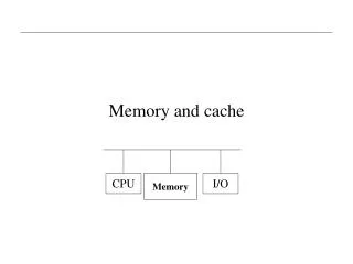
First Verilog Project (Cache Memory). Some explanation of the direct mapped cache model. Overall Structure:. Cache Structure. Note: Clk input to FSM control is not shown. Hit. Miss. This is CacheDataSelect. CacheDataInputMux. 0. 1. This is DDataSelect. 0. DDataMux. 1.

E N D
First Verilog Project (Cache Memory) Some explanation of the direct mapped cache model
Cache Structure Note: Clk input to FSM control is not shown Hit Miss This is CacheDataSelect CacheDataInputMux 0 1 This is DDataSelect 0 DDataMux 1
/WCSLoadValue = READ_WAITCYCLES-1 Cache Control State Machine !Match || !Valid / nreadmiss++ !WSCSig/ READ READMISS READMEM Dstrobe && DRW / WSCSig/ !Dstrobe/ Match && Valid/ READDATA IDLE WRITEDATA Match && Valid / WRITEHIT Dstrobe && !DRW / /nwritehits++ WRITE / WCSLoadVal = WRITE_WAITCYCLES -2; WRITEMEM WSCSig/ WRITEMISS !Match || !Valid / /nwritemiss++ !WSCSig/
Cache Controller--States • IDLE: no memory access underway • READ: Read access initiated by driver; Cache is checked during this state. If hit, access is satisfied from cache during this cycle and control returns to IDLE state at next transition. If miss, transition to READMISS state to initiate main memory access • READMISS: Initiate memory access following a read miss. Wait state counter is loaded to time the wait for completion of the main memory access. Transition to READMEM State. • READMEM: Main memory read in progress. Remain in this state until wait state counter expires then transition to READDATA state. (Main memory read requires READ_WAITCYCLES cycles to complete) • READDATA: Data available from main memory read. Write this data into the cache line and use it to satisfy the original processor (driver) read request
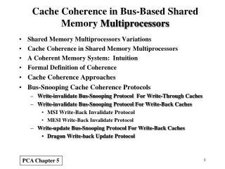
Cache Controller States--Continued • WRITE: Write access initiated by Driver. If cache is hit, transition to WRITEHIT state. If miss, transition to WRITEMISS state. • WRITEHIT: Cache has been hit on a write operation. Complete write to cache and initiate write-through to main memory. Load wait state counter to time main memory access waiting period. Transition to WRITEMEM state. • WRITEMISS: Cache has been missed on a write operation. Write to cache (cache load) and initiate write-through to main memory Load wait state timer to time main memory waiting period • WRITEMEM: Main memory write in progress. Wait for expiration of wait state counter, then transition to WRITEDATA state. • WRITEDATA: Last Cycle of Main memory write. Assert Ready signal to Driver to indicate completion of write.
Cache Control—Signals Asserted • IDLE: none • READ: DReadyEnable, DDataOE, Hit (if read hit) • READMISS: Miss, WSCLoad, MStrobe, MRW, DDataOE • READMEM: MRW, DDataOE • READDATA: Ready, Write, MRW, CacheDataSelect, DDataSelect, DDataOE • WRITE: DReadyEnable • WRITEHIT: Hit, WSCLoad, Write, MStrobe, CacheDataSelect,DDataSelect, MDataOE • WRITEMISS: Miss, WSCLoad, Write, MStrobe, MDataOE • WRITEMEM: MDataOE • WRITEDATA: Ready, CacheDataSelect, DDtataSelect, MDataOE Note: Signals Hit and Miss are not shown on the diagrams or used in the implementation of the direct mapped cache. You may use these signals if You find them helpful. Note: Signals shown in blue appear to be “don’t cares”—i.e. their assertion during the indicated cycle has no effect.
Explanation of the DReady Signal • In module CacheControl, the output DReady is controlled by a “continuous assignment” of the form: • wire DReady = (DReadyEnable && Match && Valid && DRW) || Ready; • This is equivalent to: DReadyEnable AND Match Valid DReady OR DRW Ready
Increasing the Cache Line Size • The assignment requires you to increase the cache line size from one word to two words. • The memory bus width will remain one word wide • So two memory reads will be required for cache loads following a read miss • For a cache load following a write miss, only one memory read will be required. WHY??
Some Additional Pointers • You should not need to mess with the driver module (driver1.v) • You should not need to mess with (or even understand the internals of) the main memory module (hashmem.v) • You will need to modify the cache controller (control.v). • Be certain that you thoroughly understand the finite-state machine that it implements before you start messing with it. • You should not need to add any new inputs or outputs to the FSM, but may do so if you desire
Modified Cache Control State Machine /WCSLoadValue = READ_WAITCYCLES-1 !WSCSig/ !Match || !Valid / nreadmiss++ READ READMISS READMEM1 WSCSig/ READDATA1 Dstrobe && DRW / !Dstrobe/ Match && Valid/ READDATA2 READMEM2 IDLE (write hit path) (write miss path) Match && Valid / WRITEHIT Dstrobe && !DRW / WRITEDATA /nwritehits++ WRITE / WCSLoadVal = WRITE_WAITCYCLES -2; WRITEMEM WSCSig/ WRITEMISS !Match || !Valid / /nwritemiss++ !WSCSig/ Note: This is for conceptual purposes only. Additional states may be needed to differentiate paths