Download
1 / 72
720 likes | 925 Vues
Introduction and Development Process. Peter Gorm Larsen. Agenda. Administrative information about the course What are VDM models and how are they validated? Suggested Projects to undertake The Process using the VDM++ and UML combination. Who is the teacher?. Peter Gorm Larsen ; MSc, PhD

E N D
Introduction and Development Process Peter Gorm Larsen Introduction and Development Process
Agenda • Administrative information about the course • What are VDM models and how are they validated? • Suggested Projects to undertake • The Process using the VDM++ and UML combination Introduction and Development Process
Who is the teacher? • Peter Gorm Larsen; MSc, PhD • 18 years of professional experience • ½ year with Technical University of Denmark • 13 years with IFAD • 3,5 years with Systematic • 3/4 year with University College of Aarhus • Consultant for most large defence contractors on large complex projects (e.g. JSF) • Relations to industry and academia all over the world • Has written books and articles about VDM • See http://home0.inet.tele.dk/pgl/peter.htm for details Introduction and Development Process
Contacting Details • The most convenient way - email pgl@iha.dk • Or see me in my office. I live in at IHA in Room 413c. Introduction and Development Process
Teaching Material • John Fitzgerald, Peter Gorm Larsen, Paul Mukherjee, Nico Plat and Marcel Verhoef: Validated Designs for Object-oriented Systems. Springer Verlag, 2005. • Tool used during the course http://www.vdmbook.com/tools.php • Setup.exe files and documentation can also be found under K:\from eit_staff to eit_stud\PGL • Rational Rose for UML models to be requested from K:\from eit_staff to eit_stud\PGL • Run hostinfo.exe and send me the host name and hostid such that I can generate a license file for you Introduction and Development Process
TIVDM1 web pages • All information concerning this course including lecture notes, assignments announcements, etc. can be found on the TIVDM1 web pages http://kurser.iha.dk/eit/tivdm1/ • You should check this site frequently for new information and changes. It will be your main source of information for this unit. The layout of the WebPages should be fairly self explanatory • Campus WebPages will be used only for mailing information Introduction and Development Process
Education Form • Confrontation with the teacher • Tuesdays 14:30 – 15:45 in Room 424 • Thursdays 13:00 – 15:45 in Room 424 • Read in advance of each lecture • Combination of • Lessons teaching theory • Strategy for lessons: quick intro to concepts and then usage in larger examples • Projects where theory is turned into practice • Using VDMTools for projects • Exam form • 15 minutes oral examination without preparation + 5 minutes for evaluation on the 7th of June 2006 • Oral examination will be centered around projects performed • Projects will be reused and extended further in TIVDM2 Introduction and Development Process
Focus in this course • Focus is on • Abstract modeling of realistic systems • Understanding the VDM concepts • Learning how to read models made in VDM++/UML • Learning how to write models in VDM++/UML • Learning how to validate these models • Focus is not on • Toy examples • Concurrency • Real-time requirements • Implementation Introduction and Development Process
Why have this course? • To understand the underlying primitives for being able to model complex computer systems • To be able to comprehend the formulation of important desirable properties precisely • To be able to express important desirable properties precisely • To enable the formulation of abstract models in an industrially applicable formal notation • To validate those models to increase confidence in their correctness Introduction and Development Process
Where is this used? • Modeling critical computer systems e.g. for industries such as • Avionics • Railways • Automotive • Nuclear • Defense • I have used this industrially for example at: • Boeing, Lockheed-Martin (USA) • British Aerospace, Rolls Royce, Adelard (UK) • Matra, Dassault, Aerospatiale (France) • … Introduction and Development Process
Industrially Inspired Examples • Chemical Plant Alarm Management System • A Robot Controller • A Road Congestion Warning System Introduction and Development Process
Structure of the course • Introduction and development process (chap 1+2) • VDMTools and logic (chap 3) • Defining data and functionality (chap 4 + 5) • Modeling using unordered collections (chap 6) • Modeling using ordered collections (chap 7) • Modeling relationships (chap 8) • Course evaluation and repetition Introduction and Development Process
An email from an old (very good) student … At that time I understood that a formal specification would be an advantage for big projects but I had no idea how desperately this is also needed in smaller projects when there are many people involved. Today I do know: At the moment I am working at BMW in the communications department. We work on the integration of the car telephone (including a telematics unit with GPS coordinates) into the overall car. There is a lot of interaction between the telephone and the HMI of the car and there are different versions and types of all the involved devices. There are also five companies (BMW, Motorola, Siemens VDO, Harmann-becker, Alpine) who develop the different units. The system should not be so complex because many of the devices should (!) behave similarly. But the specifications we write are English plain text (hundreds of pages), in our department more than 10 people are involved and we do not know anymore how the devices will behave ourselves...every external company has an own interpretation of the specs and this interpretation changes over time. If you ask the same person twice you get different answers (I frankly admit that I am no exception)... You can imagine how "efficient" everything is and its a miracle that the system still works (with a number of bugs though)... Introduction and Development Process
Agenda • Administrative information about the course • What are VDM models and how are they validated? • Suggested Projects to undertake • The Process using the VDM++ and UML combination Introduction and Development Process
Vienna Development Method • Invented at IBM’s labs in Vienna in the 70’s • VDM-SL and VDM++ • ISO Standardisation of VDM-SL • VDM++ is an object-oriented extension • Model-oriented specification: • Simple, abstract data types • Invariants to restrict membership • Functional specification: • Referentially transparent functions • Operations with side effects on state variables • Implicit specification (pre/post) • Explicit specification (functional or imperative) Introduction and Development Process
Validation Techniques • Inspection: organized process of examining the model alongside domain experts. • Static Analysis: automatic checks of syntax & type correctness, detect unusual features. • Testing: run the model and check outcomes against expectations. • Model Checking: search the state space to find states that violate the properties we are checking. • Proof: use a logic to reason symbolically about whole classes of states at once. Introduction and Development Process
C++ or Java interface code Validation via Animation Execution of the model through an interface. The interface can be coded in a programming language of choice so long as a dynamic link facility (e.g. CORBA) exists for linking the interface code to the model. Formal model Interface Interpreter Testing can increase confidence, but is only as good as the test set. Exhaustive techniques could give greater confidence. Introduction and Development Process
Agenda • Administrative information about the course • What are VDM models and how are they validated? • Suggested Projects to undertake • The Process using the VDM++ and UML combination Introduction and Development Process
Possible projects • SAFER • Production Cell • Cash Dispenser • CyberRail • Conveyor belt from “Automation BSc course” • Projects from “Distributed Real-Time Systems” • Projects from “Specification of IT Systems” • Suggest your own project Introduction and Development Process
SAFER Overview Introduction and Development Process
SAFER References • Simplified Aid For EVA Rescue • Presentation about mishap for SAFER • A 25 pages description of the system • Modelling SAFER using VDM-SL • Article about the SAFER VDM-SL model • VDM-SL + Mathematica simulation • Another CORBA interface to the VDM-SL model • A VDM++ model of SAFER • Article about the VDM++ model of SAFER Introduction and Development Process
Production Cell Overview Introduction and Development Process
Production Cell References • Citations for the book about this • Project assignment from AUC/DTU about this • Slides about Production cell in different formalism • A book with a comparative study Introduction and Development Process
Cash Dispenser Overview Introduction and Development Process
The Cash Dispenser Model • Model of a system of tills and a central resource. • Customers interact with tills by inserting a card and entering a PIN • Central resources contains detailed records of customers’ bank accounts • “Illegal” cards are kept by the till. Introduction and Development Process
A Cash Dispenser Example Tills Central Repository Introduction and Development Process
Requirement Specification • There are many tills which can access a central resource containing the detailed records of customers’ bank accounts. A till is used by inserting a card and typing in a PIN (Personal Identification Number) which is encoded by the till and compared with a code stored on the card. After successfully identifying themselves to the system, customers may try to: • 1. view the balance of their accounts • 2. make a withdrawal of cash • 3. ask for a statement of their account to be sent by post. • Information on accounts is held in a central database and may be unavailable. In that case 1) above may not be possible. If the database is available, any amount up to the total in the account may be withdrawn, subject to a fixed daily limit on withdrawals. This means that the amount withdrawn within the day must be stored on the card. “Illegal” cards are kept by the till. Introduction and Development Process
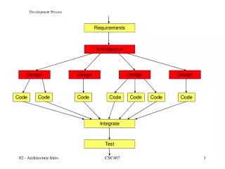
Analysis (using VDM-SL with API animation) alternative to use cases abstraction from multiple tills Design (using Rose VDM++ Link with systematic testing and API animation) abstraction from possible failures of tills Implementation (with concurrent VDM++ model and automatic Javacode generation combined with user interface) Development Process Introduction and Development Process
Clock Till CentralResource date : Date cardOk : bool = false illegalCards : set of Card`CardId = {} -clock GetDate() numberOfTries : map Card`CardId to nat = {|->} Create() SetDate() maxNumberOfTries : nat = 3 Validate() CardInside() Letterbox Create() GetBalance() -resource -letterbox AddAccount() InsertCard() GetBalance() ReturnCard() PostStatement() Withdrawal() IsLegalCard() GetLastStatement() IsLegalCard() CardValidated() PostStatement() MakeWithdrawal() AddIllegalCard() RequestStatement() IncrNumberOfTries() Encode() {ordered} ResetNumberOfTries() -statements 0..* 0..* NumberOfTriesExceeded() Account`AccountId Account`AccountId Letter date : Clock`Date -accounts name : Cardholder`Name Account address : Cardholder`Address -curCard -retainedCards balance : nat balance : nat 0..* 0..* 0..1 0..1 transactions : seq of Account`Transaction transactions : seq of Transaction = [] Card dailyLimit : nat = 2000 Create() code : Code Create() cardId : CardId AddCard() accountId : Account`AccountId Cardholder GetBalance() GetCardIds() name : Name GetCode() Withdrawal() address : Address GetCardId() Card`CardId Card`CardId MakeStatement() GetAccountId() ValidTransaction() Create() Create() -cards Sum() GetName() TransactionsInvariant() GetAddress() DateTotal() UML Class Diagram Introduction and Development Process
Cash Dispenser References • The Cash Dispenser Example at different abstraction levels • The VDM++ non-concurrent version of the Cash Dispenser model • The VDM++ Concurrency version of the Cash Dispenser model Introduction and Development Process
CyberRail Overview Introduction and Development Process
CyberRail References • The CyberRail web page • CyberRail, Concept and Future • CyberRail articles from web page Introduction and Development Process
Conveyor belt Introduction and Development Process
Components and Control • Components • M1: Engine to pull the belt forward or backward. • Speed control: Indication that the belt is running. • Cylinder 1 and 2: Pneumatic cylinders for moving off bricks. • Switch 1 and 2: Indication of cylinder 1’s position. • Switch 3 and 4: Indication of cylinder 2’s position. • Barcode reader: Reads the bar code on a brick. • Photo cell 1: Register a brick right after the bar code reader. • Photo cell 2: Register a brick right before discard 1. • Photo cell 3: Register a brick right before discard 2 • Control • Operator selection of sorting principles • Alarms for cylinders • Alarm if the belt stops while processing is ongoing • Alarm is photo cell discover bricks that have not been processed by bar code reader Introduction and Development Process
System-level functionality in VDM-SL types Stream = seq of Brick; Brick :: code : Code color : <Red> | <Green> | <Yellow>; Code = token; functions ConveyorBelt: Stream * Code * Code -> Stream * Stream * Stream ConveyorBelt(input,code1,code2) == mk_([input(i) | i in set inds input & input(i).code = code1], [input(i) | i in set inds input & input(i).code = code2], [input(i) | i in set inds input & input(i).code not in set {code1,code2}]) Introduction and Development Process
Establishments of Groups • For each of these possible projects the participants should go together to form small groups of 2 to 3 persons per group • Groups should decide this week which project to work on during this course • Every week (2 – 6) every group will present to the entire class how their project is getting along • The project will be further extended and analyzed with concurrency and real-time aspects in the TIVDM2 course Introduction and Development Process
Anticipated Plan with Projects • Week 2: Read existing material about the project and formulate a new requirements definition for the project to undertake with focus on the purpose of the model to develop • Week 3: Complete UML class diagram for the project with signatures for operations/functions • Week 4+5: Model and validate functionality using VDM++ • Week 6: Report with the project is handed in to the teacher • Week 7: Evaluation of insight gained by using the model-driven approach combining VDM++ and UML Introduction and Development Process
Agenda • Administrative information about the course • What are VDM models and how are they validated? • Suggested Projects to undertake • The Process using the VDM++ and UML combination Introduction and Development Process
Steps to Develop a Formal Model • Determine the purpose of the model. • Read the requirements. • Analyze the functional behavior from the requirements. • Extract a list of possible classes or data types (often from nouns) and operations (often from actions). Create a dictionary by giving explanations to items in the list. • Sketch out representations for the classes using UML class diagrams. This includes the attributes and the associations between classes. Transfer this model to VDM++ and check its internal consistency. • Sketch out signatures for the operations. Again, check the model's consistency in VDM++. • Complete the class (and data type) definitions by determining potential invariant properties from the requirements and formalizing them. • Complete the operation definitions by determining pre- and post conditions and operation bodies, modifying the type definitions if necessary. • Validate the specification using systematic testing and rapid prototyping. • Implement the model using automatic code generation or manual coding. Introduction and Development Process
A Chemical Plant alarm expert Introduction and Development Process
A Chemical Plant Requirements • A computer-based system is to be developed to manage the alarms of this plant. • Four kinds of qualifications are needed to cope with the alarms: electrical, mechanical, biological, and chemical. • There must be experts on duty during all periods allocated in the system. • Each expert can have a list of qualifications. • Each alarm reported to the system has a qualification associated with it along with a description of the alarm that can be understood by the expert. • Whenever an alarm is received by the system an expert with the right qualification should be found so that he or she can be paged. • The experts should be able to use the system database to check when they will be on duty. • It must be possible to assess the number of experts on duty. Introduction and Development Process
The Purpose of the VDM++ Model The purpose of the model is to clarify the rules governing the duty roster and calling out of experts to deal with alarms. Introduction and Development Process
Creating a Dictionary • Potential Classes and Types (Nouns) • Alarm: required qualification and description • Plant: the entire system • Qualification (electrical, mechanical, biological, chemical) • Expert: list of qualifications • Period (whatever shift system is used here) • System and system database? This is probably a kind of schedule. • Potential Operations (Actions) • Expert to page: when an alarm appears (what's involved? Alarm operator and system) • Expert is on duty: check when on duty (what's involved? Expert and system) • Number of experts on duty: presumably given period (what's involved? operator and system) Introduction and Development Process
Guideline 1 Nouns from a dictionary should be modeled as types if, for the purposes of the model, they need have only trivial functionality in addition to read/write. Introduction and Development Process
Sketching an Alarm Defined as a VDM++ class: class Alarm instance variables reqQuali: Expert`Qualification descr : String; end Alarm Introduction and Development Process
Alternative Alarm Alarm could also have been defined as a composite type: Alarm :: reqQuali : Expert`Qualification descr : String Then if a is of type Alarm: a.descr is the description of a a.descr : String a.reqQuali : Expert`Qualification Introduction and Development Process
Guideline 2 Create an overall class to represent the entire system so that the precise relationships between the different classes and their associations can be expressed there. Introduction and Development Process
Guideline 3 and 4 Whenever an association is introduced consider its multiplicity and give it a rôle name in the direction in which the association is to be used. If an association depends on some value, a qualifier should be introduced for the association. The name of the qualifier must be a VDM++ type. Introduction and Development Process
Initial Class Diagram class Plant instance variables public alarms : set of Alarm; public schedule : map Period to set of Expert; end Plant Introduction and Development Process
Guideline 5 Declare instance variables to be private or protected to keep encapsulation. If nothing is specified by the user, private is assumed automatically. class Expert instance variables private quali: set of Qualification; end Expert class Alarm instance variables private descr : String; private reqQuali: Qualification; end Alarm Introduction and Development Process