Download
1 / 40
470 likes | 1.1k Vues
CP504 – ppt_Set 10. Sterilization (continued). Learn about thermal sterilization of liquid medium Learn about air sterilization (only the guidelines) Learn to do design calculations. Continuous Sterilization:. Simplifies production planning

E N D
CP504 – ppt_Set 10 Sterilization (continued) • Learn about thermal sterilization of liquid medium • Learn about air sterilization (only the guidelines) • Learn to do design calculations
Continuous Sterilization: • Simplifies production planning • Therefore gives maximum plant utilization and minimum delays • Provides reproducible conditions • Can be operated at high temperature (1400C) • Therefore sterilization time can be reduced (2 to 3 min) • Requires less steam and less cooling water • Suitable when the capacity of operation is high • High initial capital investment (use of aseptic transfer system for the sterile broth to be transported to a sterile vessel)
Continuous Sterilization: It is the only option if the medium is to be exposed to high temperatures for a short time (HTST process) to avoid denaturation of proteins or to avoid destruction of some of the enzymes, etc., since it is not possible in commercial scale operations in batch sterilization to quickly heat large volumes of the medium in short time and cool it also in short times.
Continuous Sterilization: Continuous Injection Type Steam Raw medium Expansion valve vacuum Holding section (where most of the sterilization takes place) Flash cooler - Direct steam injection for heating (relatively a rapid process) - Flash cooling (rapid process) Sterile medium
Continuous Sterilization: Continuous Injection Type • Capital investment is low • Easy to clean and maintain the system • Heating and cooling periods are shorter • Steam efficiency is very high as live steam is directly injected into the medium • Direct contact of the steam with the medium makes it necessary that the steam should be clean and free of any anti-corrosive agents • Foaming may occur during both heating and cooling
Continuous Sterilization: Continuous Heat Exchanger Type Sterile medium Steam Holding section Indirect steam heating in plate-and-frame (or shell-and-tube) heat exchanger Raw medium Cooling water
Continuous Sterilization: Continuous Heat Exchanger Type plate-and-frame heat exchanger has larger heat transfer area than shell-and-tube heat exchanger, and therefore more effective plate-and-frame heat exchanger is favourable with high viscous system plate-and-frame heat exchanger is limited to lower pressures (less than 20 atm) due to its weak structural strength
Continuous Sterilization: Most of the sterilization in the continuous sterilization process may occur in the holding section. Therefore no hold ln = kdλhold = kd0 exp(-Ed/RT) λhold = nt Since the holding section is a long pipe, length of the pipe L uav λ = hold average fluid velocity in the pipe
Continuous Sterilization: The ratio of average velocity to maximum velocity uav 0.5 for laminar flow of Newtonian fluids through a smooth round pipe = umax 0.75 for turbulent flow = 0.87 for turbulent flow with the Reynolds Number of 1000,000 = Therefore, using the average velocity to calculate the length of the pipe required for sterilization may leave some portion of the medium understerilized, which may cause contamination problem
Example 10.4: Estimating the time required for continuous sterilization A continuous sterilizer with a steam injector and a flash cooler will be employed to sterilize medium continuously with the flow rate of 2 m3/h. The time for heating and cooling is negligible with this type of sterilizer. The typical bacterial count of the medium is about 5 x 10¹² per m3, which needs to be reduced to such an extent that only one organism can survive during two months of continuous operation. The sterilizer will be constructed with the pipe with an inner diameter of 0.102 m. Steam at 600 kPa (gauge pressure) is available to bring the sterilizer to an operating temperature of 125oC. For the heat resistant bacterial spores: kdo = 5.7 x 1039 per h; Ed = 2.834 x 10⁵ kJ / kmol. For the medium: c = 4.187 kJ/kg.K; ρ= 1000 kg/m3; μ= 4 kg/m.h. a) What length should the pipe be in the sterilizer if you assume ideal plug flow? b) What length should the pipe be in the sterilizer if the effect of axial dispersion is considered? Assume an axial dispersion coefficient of 20 m2/h.
t n0 kd dt ln = = nt 0 Solution to Example 10.4: Problem statement: The typical bacterial count of the medium is about 5 x 10¹² per m3, which needs to be reduced to such an extent that only one organism can survive during two months of continuous operation. n0= (5 x 10¹² per m3) x (2 m3/h) x (24 h/day) x (60 days) =14400 x 1012 nt = 1 144x1014 = 37.2 = ln 1 The above integral should give 37.2.
Solution to Example 10.4: a) Since the temperature at the holding section in constant, hold = kdλhold = 37.2 For the given data, kd = kd0 exp(-Ed/RT) = (5.7 x 1039 per h) exp[- 2.834x10⁵/ 8.314x(273.15+125)] = 375.3 per h Therefore, λhold= 37.2 / kd = 37.2 / 375.3 per h = 0.099 h Length of the pipe, L = velocity through the pipe x λhold = velocity through the pipe x 0.099 h
Solution to Example 10.4: Since plug flow is assumed, velocity through the pipe = 2 m3/h = 245 m/h π (0.102/2)2 m2 Therefore, L = (245 m/h) x (0.099 h) = 24.26 m What happens if the flow is not plug flow?
Solution to Example 10.4: b) If axial dispersion is considered, then we use the following table: uav L D Peclet number = nt Axial dispersion coefficient n0 kd L uav
Solution to Example 10.4: (245 m/h) x ( L m) (20 m2/h) uav L D = Peclet number = kd L uav (375.3 per h) x ( L m) (245 m/h) = X-coordinate = nt n0 is obtained from the table Y-coordinate =
Solution to Example 10.4: If L = 25 m is tried, we get (245 m/h) x ( 25 m) (20 m2/h) uav L D = 306 = Peclet number = kd L uav (375.3 per h) x ( 25 m) (245 m/h) = 38.3 = X-coordinate = nt n0 = 2 x 10-15 Y-coordinate = Data provided: n0=14400 x 1012; nt = 1 Therefore, required nt / n0=6.9 x 10⁻¹⁷ Calculated ratio > Required ratio
Solution to Example 10.4: If L = 27.5 m is tried, we get (245 m/h) x ( 27.5 m) (20 m2/h) uav L D = 337 = Peclet number = kd L uav (375.3 per h) x ( 27.5 m) (245 m/h) = 42.1 = X-coordinate = nt n0 6.9 x 10⁻¹⁷ ≈ Y-coordinate =
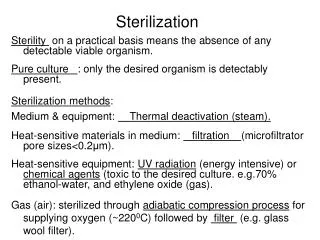
Filtration: Sterilize solutions that may be damaged or denatured by high temperatures or chemical agents. The pore size for filtering bacteria, yeasts, and fungi is in the range of 0.22-0.45 μm The pore size for filtering viruses and some large proteins is in the range of 0.01 μm
Methods for gas (air) sterilization: • Aerobic fermentation require huge volumes of air (a 50,000 L fermenter requires 7x10⁶ to 7x10⁷ L per day of air) which must be sterilized. • Adiabatic compression of process air can increase air temperature (150oC to 220oC). A temperature typically of 220oC for 30 s is required to kill spores. • An air-filtration step is almost always used to ensure sterility of process air. • Depth filters use glass wool, and rely on inertial impaction, interception, diffusion and electrostatic attraction (explained later). • Surface filters using membrane cartridges use the sieving effect (explained later).
Filtration mechanisms operating in depth filters http://blogs.cdc.gov/niosh-science-blog/2009/10/n95/
Filtration mechanisms operating in depth filters Inertial impaction (or impingement) occurs when a particle travelling in the air stream and passing around a fibre, deviates from the air stream (due to particle inertia) and collides with the fibre. Impaction is the dominant collection mechanism for particles larger than 0.2 μm. It is important in removing bacteria.
Filtration mechanisms operating in depth filters Interception occurs when a large particle, because of its size, collides with a fibre in the filter that the air stream is passing through. Interception is the dominant collection mechanism for particles greater than 0.2 μm. It is important in removing bacteria.
Filtration mechanisms operating in depth filters Diffusion occurs when the random (Brownian) motion of a particle causes that particle to contact a fibre. Diffusion is dominant for particles less than 0.2 μm. It may be important for virus removal, but bacteria are sufficiently large that diffusion is relatively unimportant.
Filtration mechanisms operating in depth filters Electrostatic attraction plays a very minor role in mechanical filtration. After fibre contact is made, smaller particles are retained on the fibres by a weak electrostatic force.
Filtration mechanisms operating in surface filters http://www.renewableenergy.nl/index.php?pageID=3220&n=545&itemID=351064
Filtration mechanisms operating in surface filters http://www2.donaldson.com/torit/en-us/pages/technicalinformation/mistcollection_fundandapp.aspx
Stirred tank bioreactor – Oxygen delivery system: The oxygen delivery system consists of • a compressor • inlet air sterilization system • an air sparger • exit air sterilization system
Stirred tank bioreactor – Oxygen delivery system: • A compressor forces the air into the reactor. The compressor will need to generate sufficient pressure to force the air through the filter, sparger holes and into the liquid. • Air compressors used for large scale bioreactors typically produce air at 250 kPa. The air should be dry and oil free so as to not block the inlet air filter or contaminate the medium. • Note that it is very important that an "instrument air" compressor is not used. Instrument air is typically generated at higher pressures but is aspirated with oil. Instrument air compressors are used for pneumatic control.
Stirred tank bioreactor – Air sterilization: • Sterilization of the inlet air is undertaken to prevent contaminating organisms from entering the reactor. • The exit air on the other hand is sterilized not only to keep contaminants from entering but also to prevent organisms in the reactor from contaminating the air. • A common method of sterilising the inlet and exit air is filtration. • For small reactors (with volumes less than 5 litres), disk shaped hydrophobic Teflon membranes housed in a polypropylene housing are used. Teflon is tough, reusable and does not readily block.
Stirred tank bioreactor – Air sterilization: • For larger laboratory scale fermenters (up to 1000 litres), pleated membrane filters housed in polypropylene cartridges are used.
Stirred tank bioreactor – Air sterilization: • By pleating the membrane, it is possible to create a compact filter with a very large surface area for air filtration. Increasing the filtration area decreases the pressure required to pass a given volume of air through the filter. • Sterilization of the inlet and exit air in large bioreactors (> 10,000 litres) can present a major design problem. Large scale membrane filtration is a very expensive process. The filters are expensive as they are difficult to make and the energy required to pass air through a filter can be quite considerable.
Stirred tank bioreactor – Air sterilization: • Heat sterilization is alternative option. • Steam can be used to sterilize the air. • With older style compressors, it was possible to use the heat generated by the air compression process to sterilize the air. • However, compressors are now multi-stage devices which are cooled at each stage and disinfecting temperatures are never reached.
Air sterilization – positive pressure: • During sterilisation, the concept of "maintaining positive pressure" will often be used. • Maintaining positive pressure means that during sterilisation, cooling and filling and, if appropriate, the fermentation process, air must be pumped into the reactor. • In this way the reactor is always pressurised and thus aerial contaminants will not be "sucked" into the reactor.
Air sterilization – positive pressure: With aeration, positive pressure is always maintained and contaminants are pushed away from the reactor Without aeration, a vacuum forms as the reactor cools.
Stirred tank bioreactor - Cleaning and sterilization facilities: • Small scale reactors are taken apart and then cleaned before being re-assembled, filled and then sterilized in an autoclave. • However, reactors with volumes greater than 5 litres cannot be placed in an autoclave and sterilized. These reactors must be cleaned and sterilized "in place". This process is referred to "Clean in Place” (CIP). • CIP involves the complete cleaning of not only the fermenter but also all lines linked to the internal components of the reactor. Steam, cleaning and sterilizing chemicals, spray balls and high pressure pumps are used in these processes. The process is usually automated to minimize the possibility of human error.
Concerns in air sterilization: Pressure drop is critical in a filter. Energy input for compressed air for a commercial-scale process is significant. Air treatment can account for 25% of total production costs. Design engineer has to balance the assurance sterility against the pressure drop.
180M3 Fermenter Plant Air Compressor