Download
1 / 17
180 likes | 304 Vues
REVIEW OF QUENCH HEATERS FOR LHC. A view on development and manufacturing experience at CERN. Felix Rodriguez Mateos, TE-MPE. Outline. The definition of QH for LHC General view on principles Scale factors Layout and redundancy Validation Manufacturing methods

E N D
REVIEW OF QUENCH HEATERS FOR LHC A view on development and manufacturing experience at CERN Felix Rodriguez Mateos, TE-MPE
Outline • The definition of QH for LHC • General view on principles • Scale factors • Layout and redundancy • Validation • Manufacturing methods • Co-lamination of steel strips and composite foils • Copper cladding • Connection to leads • Feedback from series production • Reported problems • Conclusions • References
General view on principles Quench Protection Magnet Design HEATER COIL • Cable characteristics (quench capacity) • Current (density in copper) • Magnet inductance and couplings • B field distribution • External circuit and decay time constant (quench load) • Number of turns heated (B field) –heater width • Heater circuit and specific power • Insulation thickness • Longitudinal heat distribution (cladding, stations etc– layout) • Total resistance at cold Analysis, tests and validation Model magnet tests Numeric simulations: HEATER DELAY Prototype tests
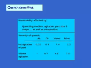
Scale factors: How to go from a short to a long magnet? • Time constant for the current decay in a short or a long magnet protected with heaters is basically the same • The specific power on heater should be also the same as to guarantee the same delays • Once the design is fixed, heater delays are the overall parameter governing the reaction of the magnet, as once they are effective, joule heating in coil exceeds by far the heating from the heater itself R long= fR short U long = f U short for equal specific power [W/cm2] • The question to answer is: do we have enough voltage withstand capability as to power the heater with a voltage f times larger?
Layout and redundancy • Iterations during the coil design phase using simulation programs QUABER and SPQR • QUABER used heater delays as input (values coming from tests with model magnets) • SPQR could calculate heater delays in a FD model including the effect from helium cooling • Systematic heater tests for every one of the model/prototype/series magnets – many heater configurations were tested (heater width, plating cycles, insulation thickness, etc.) • The requirement for quenching the magnets by heaters at low current was defined at injection current (although it was known that heaters were not really required below 2 kA) • HF and LF heaters were supposed to be redundant ones with respect to the others
Validation (1) QUABER SPQR The average heater delays (spread ±5 ms) from simulations and experiments are compared for the high-field heaters in a dipole magnet. The test set-up was equivalent to a power supply voltage of 900V feeding two 15m long heater strips connected in series. Uminis the minimum heater voltage required to provoke a quench at injection current.
Validation (2) Quench load versus current for different heater protection schemes in an LHC dipole prototype (MBP2N1-V2). Note that quenches were provoked by spot heaters. Quench load versus current for different heater protection schemes of the SSS3 prototype. Note that all quenches were provoked by firing a quench heater strip. Limit had been set to 30 MA2s
Manufacturing method • The first generation of quench heaters for the 1-m magnet models were produced at CERN with commercial dry and sticky insulation films and stainless steel strips pre-cut to final width requiring a fair amount of manual work using an assembly table with rollers to exert pressure for the bonding process. Later on, a second generation of heaters for the 1-m model magnets stainless steel sheets were produced using composite foils made of steel foils pre-laminated onto PI films, and then the heater pads were made by etching away the unnecessary steel. • For the first 10 m prototype magnets several different processes were used to bond the pre-cut stainless steel strips manually onto the carrier and the cover foils. • By the end of the 90’s, CERN started developing in collaboration with European industry a continuous production process in order to be able to supply the finally needed quantity of some 150 km of quench heaters. The basic idea was to feed the top and bottom insulation layer with an epoxy adhesive and in between the partially copper plated steel strips into a continuous roller press arrangement which exerts pressure and heat. • Subsequently, the perimeter of the quench heater sandwich is cut to the required shape and formed to adapt to the pole face of the coil together with the ground insulation. • Wires and fixation plates are soft soldered to the ends of the quench heater strips. Windows cut by laser are provided to this purpose
Copper cladding procedure • Degreasing by ultrasonic bath and detergent over 5 minutes • Rinsing with water • Electrolytic degreasing (1 min, 5 V) • Rinsing with water • Sulphuric inversion (30 s, 5 V) • Rinsing with water • Surface etching by Hydrochloricacid (1 min) • Application of a Wood Nickel layer (1 min at 2 V) • Rinsing with water • Copper plating (copper Sulfate, no brilliance) (10 min at 0.5/dm2 – around 1 V) • Rinsing with water • Passivation by Chromic acid (5 s) • Rinsing with de-mineralised water • Rinsing with alcohol • Dry and bake out • A procedure was developed at CERN that afterwards was improved at companies in order to eliminate the nickel layer • It was demonstrated analytically that a Ni layer in the order of a micron (or submicron) at the heater positions would have no influence on the magnetic field at the bore • One of the issues with copper plating for cryogenic applications is that the RRR depends on thickness and RRR values in the order of 20 are desirable • RRR of the steel is also not to be neglected (it was the reason for an amendment to the initial contract) Procedure developed at CERN by the Surface and Coatings Laboratory in the 90’s
Connection to leads • it was a delicate operation from the very beginning • initially, thick copper pieces were brazed to the steel strip ends; the insulation foils had to be protected from this high temperature operation • later on, it was decided to use smaller copper pieces (the so-called omegas) which would be soldered with Sn-Ag eutectic • CEA-Saclay decided to use crimped contacts in stead Alcohol or acetone are used for cleaning after soldering Pictures: A. Musso
The QH zoo in LHC • Different versions but all within the same principle : co-lamination and copper plating • Only exception are the MQ heaters which are first copper plated in a selective manner, then pads are chemically etched and finally a cover foil is laid onto the resulting product
Feedback from series production • Issues during collaring • Heater must be well positioned; especially the omegas that need to lay within the groove machined for the purpose • If not, risks that collaring process destroys the heater end • In case of re-collaring a magnet, a set of brand new QH was used because the collaring process was marking the coil outer irregularities quite strongly on the QH surface • Issues afterwards (testing the magnets, warm or cold) • Two classes of problems • Straight part (8 cases) – detected during standard electrical tests at warm • Ends (12 cases) – 50% detected at warm during standard tests; 50 % at CERN on the bench • Straight part problems are supposed to be originated by defects in the heater themselves • Ends problems were identified by possible mistakes during assembly (collaring)
Fixation of QH during collaring Pictures: A. Musso • Failure in the straight part Pictures: M. Bajko
Failure in the coil end • The critical area for the quench heaters QH marked by the coil protection sheets Accidental overlapping of two coil protection sheets Pictures: M. Bajko Shear stresses appear between QH and coil during Collaring process Cool down Power cycles and quenches The somehow curved profile that the heater has to follow in the transition from the regular length of the coil to adapt to the grooves machined for the omegas in the end spacers is not helping on this
Conclusions • Initially, burrs on the metallic strips were expected to be a major problem: behaving like knives, cutting the heater insulation, and likely provoking shorts to coils – this problem has not been detected • The problem as usual appeared to be at the interface: the connections • Assembly issues should be considered from the very beginning of the design phase • It is crucial to properly analyze the transition between the straight part of the heater and the connections (ends) • One has to do proper qualification of heater manufacturer (in case of a series) and make sure that the company can go through all the process long. CERN used three companies for the dipole magnets and one different for the main quadrupoles. • Always install enough redundancy in case problems come up • Think of a system for an early detection of failures (e.g. circuit interrupted due to a cut in a strip) : LHC is thinking about it now
References used here • Development of Industrially Produced Composite Quench Heaters for the LHC Superconducting Lattice Magnets LHC Project Report 48 (B. Szeless et al) • Technical Specification for the Supply of Quench Heaters for the series LHC Superconducting Main Dipole Magnets EDMS 316296 • Technical Specification for the Supply of Quench Heaters for the LHC Superconducting Main Quadrupole Magnets EDMS 114009 • Quench Heater Experiments on the LHC Main Superconducting Magnets LHC Report 418 (F Rodriguez-Mateos et al) • Quench Heater Studies for the LHC Magnets LHC Project report 485 (F Rodriguez-Mateos and F Sonnemann) • Resistive Transition and Protection of LHC Superconducting Cables and Magnets CERN-THESIS-2001-004 (F Sonnemann) • Quench Heater inspection and assembly procedure at cold mass assemblers EDMS 593927 (A. Musso) • Report on Quench Heaters failures EDMS 889445(M. Bajko et al)