Download
1 / 19
190 likes | 346 Vues
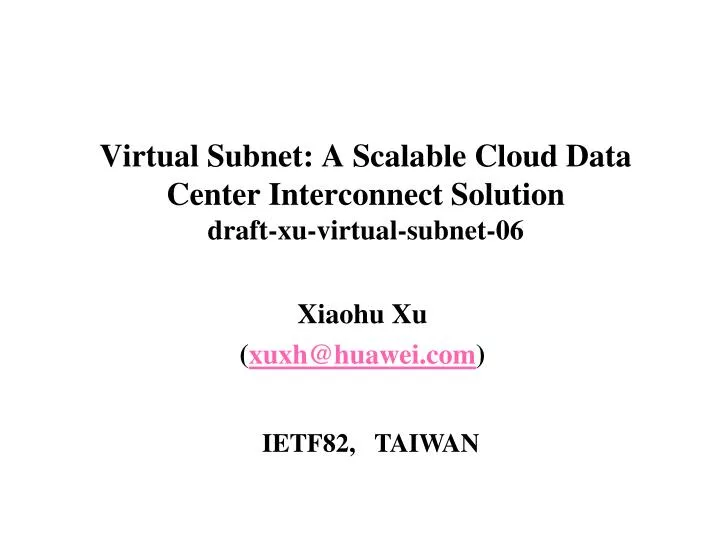
Virtual Subnet: A Scalable Cloud Data Center Interconnect Solution draft-xu-virtual-subnet-06. Xiaohu Xu ( xuxh@huawei.com ). IETF82, TAIWAN. Why VM Mobility across Data Centers. Data center maintenance

E N D
Virtual Subnet: A Scalable Cloud Data Center Interconnect Solutiondraft-xu-virtual-subnet-06 Xiaohu Xu (xuxh@huawei.com) IETF82, TAIWAN
Why VM Mobility across Data Centers • Data center maintenance • Applications on a server or data center infrastructure requiring maintenance can be migrated offsite without downtime. • Disaster avoidance: • Data centers in the path of natural calamities (such as hurricanes) can proactively migrate the mission-critical application environment to another data center. • Data center migration or consolidation: • Migrate applications from one data center to another without business downtime as part of a data center migration or consolidation effort. • Data center expansion: • Migrate virtual machines to a secondary data center as part of data center expansion to address power, cooling, and space constraints in the primary data center.
Cloud Data Center Interconnect Requirements • Subnet extension. • Allow VMs to move across data centers without requiring renumbering. • Scalability. • Multi-tenancy capability (Beyond 4K VLANs). • MAC table scalability (Millions of VMs within a data center) . • Unknown unicast reduction/avoidance • ARP broadcast reduction/avoidance. • Multi-homing. • Active-active DC exits. • Path optimization.
Virtual Subnet Overview • Virtual Subnet (VS) is a host route based IP-only L2VPN service. • BGP/MPLS IP VPN [RFC4364] signaling is used to distribute CE host routes across PE routers. Thus, the subnet is extended across data centers. • In comparison to VPLS, VS has the following advantages as a DCI solution: • Reduce MAC table size of CE switches. • Avoid flooding unknown unicast and ARP broadcast traffic across data centers. • Natural multi-homing capability. • Support active-active DC exits while guaranteeing path symmetry. • Support path optimization.
Prefix Next-hop Protocol 1.1.1.1/32 PE-1 BGP 1.1.1.2/32 PE-1 BGP 1.1.1.3/32 Local ARP 1.1.1.4/32 Local ARP 1.1.0.0/16 Null Direct PE-2 PE-1 Control Plane: Routing Table Local host route creation according to ARP cache VRF: VRF: Prefix Next-hop Protocol 1.1.1.1/32 Local ARP 1.1.1.2/32 Local ARP 1.1.1.3/32 PE-2 BGP 1.1.1.4/32 PE-2 BGP 1.1.0.0/16 Null Direct 2 4 MPLS/IP Backbone Routing table built up! 3 Host route exchange via L3VPN signaling VPN Subnet: 1.1.0.0/16 ARP Proxy ARP Proxy 1 1 Host discovery via ARP/ICMP etc. Host discovery via ARP/ICMP etc. Host D: 1.1.1.4 Host A: 1.1.1.1 Host C: 1.1.1.2 Host B: 1.1.1.3 VPN Site #1 VPN Site #2
Prefix Next-hop Protocol 1.1.1.1/32 PE-1 BGP 1.1.1.2/32 PE-1 BGP 1.1.1.3/32 Local ARP 1.1.1.4/32 Local ARP 1.1.0.0/16 Null Direct IP(A)->IP(B) IP(A)->IP(B) IP(A)->IP(B) VLAN ID VLAN ID VPN Label MAC(A)->MAC(PE-1) MAC(PE-2)->MAC(B) Tunnel to PE-2 PE-1 PE-2 Data Plane: Unicast VRF: VRF: Route look-up Route look-up Prefix Next-hop Protocol 1.1.1.1/32 Local ARP 1.1.1.2/32 Local ARP 1.1.1.3/32 PE-2 BGP 1.1.1.4/32 PE-2 BGP 1.1.0.0/16 Null Direct 4 2 MPLS/IP Backbone 3 VPN Subnet: 1.1.0.0/16 ARP Proxy ARP Proxy 1 5 Host D: 1.1.1.4 Host A: 1.1.1.1 Host C: 1.1.1.2 Host B: 1.1.1.3 Local PE returns its own MAC as ARP proxy ARP: 0 IP MAC IP(B) MAC(PE-1) VPN Site #1 VPN Site #2
IP(A)->IP(B) IP(A)->IP(B) VLAN ID VLAN ID MAC(A)->MAC(PE-1) MAC(PE-2)->MAC(B) PE-2 PE-1 MAC Table Reduction on CE Switches • The otherwise whole MAC learning domain associated with a given IP subnet, which has been extended across the MPLS/IP backbone, are partitioned into multiple isolated sub-domains. • Thus, CE switches only need to learn MAC addresses of local CE hosts and local PE routers. MPLS/IP Backbone VPN Subnet: 1.1.0.0/16 ARP Proxy ARP Proxy CE Switch CE Switch MAC learning domain #1 MAC learning domain #2 Host D Host A Host C Host B VPN Site #1 VPN Site #2
IP(A)->IP(?) VLAN ID MAC(A)->MAC(PE-1) PE-1 PE-2 Unknown Unicast Flooding Avoidance No route, no pass • No flooding of unknown unicast traffic across the IP/MPLS backbone. • Ingress PE routers forward customer packets according to the corresponding VPN routing table. MPLS/IP Backbone VPN Subnet: 1.1.0.0/16 ARP Proxy ARP Proxy Host D Host A Host C Host B VPN Site #1 VPN Site #2
PE-1 PE-2 ARP Broadcast Prevention A • No flooding of ARP broadcasts across the IP/MPLS backbone: • For an ARP request for a local CE host, discards it. • For an ARP request for a remote CE host, returns its own MAC as a response. • For an ARP request for an unknown CE host (i.e., no matching host route found), discards it. MPLS/IP Backbone B’MAC=MAC(PE-1) VPN Subnet: 1.1.0.0/16 ARP Proxy ARP Proxy Q B’MAC=? ARP broadcast domain #1 ARP broadcast domain #2 Host D Host A Host C Host B VPN Site #1 VPN Site #2
Prefix Next-hop Protocol 1.1.1.1/32 PE-1 BGP 1.1.1.1/32 PE-3 BGP 1.1.1.3/32 Local ARP 1.1.0.0/16 Null Direct PE-3 PE-1 PE-2 Site Multi-homing VRF: • Active-active multi-homing is available for inbound traffic. • Both VRRP master and VRRP slaver advertise host routes for their local CE hosts. VRF: Prefix Next-hop Protocol 1.1.1.1/32 Local ARP 1.1.1.3/32 PE-2 BGP 1.1.0.0/16 Null Direct ARP Proxy MPLS/IP Backbone VRRP Master/ ARP Proxy ECMP VPN Subnet: 1.1.0.0/16 VRRP Slave Host A: 1.1.1.1 Host B: 1.1.1.3 VPN Site #1 VPN Site #2
PE-2 PE-1 CE Host Mobility(VM Mobility) • Host route for the moved VM is updated after the gratuitous ARP is received by the current PE of the moved VM. • ARP entries for that VM cached on both routers and other CE hosts are updated. ARP Proxy ARP Proxy 4 2 Create a local host route for host C Update host route for host C BGP update for host C 3 VPN Subnet: 1.1.0.0/16 MPLS/IP Backbone Gratuitous ARP IP(C)->MAC(PE-1) 1 5 Gratuitous ARP Host C Host A Host C Host B Host C moves from Site #1 to Site #2 0 VPN Site #1 VPN Site #2
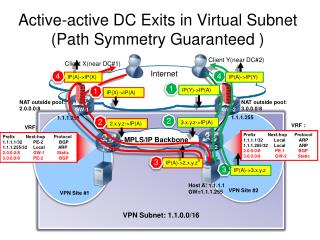
PE-1 PE-2 Active-active DC Exits (Path Symmetry Guaranteed ) Client Y(near DC#2) Client X(near DC#1) 1 1 IP(X)->IP(A) IP(Y)->IP(A) Internet 4 4 IP(A)->IP(Y) IP(A)->IP(X) NAT outside pool: 3.0.0.0/8 NAT inside pool: 2.0.0.0/8 GW-1 GW-2 1.1.1.255 1.1.1.255 VPN Subnet: 1.1.0.0/16 2 2 3.3.3.3->IP(A) 2.2.2.2.->IP(A) VRF : VRF: Prefix Next-hop Protocol 1.1.1.1/32 Local ARP 1.1.1.255/32 Local ARP 2.0.0.0/8 PE-1 BGP 3.0.0.0/8 GW-2 Static Prefix Next-hop Protocol 1.1.1.1/32 PE-2 BGP 1.1.1.255/32 Local ARP 2.0.0.0/8 GW-1 Static 3.0.0.0/8 PE-2 BGP MPLS/IP Backbone 3 IP(A)->2.2.2.2 Host A: 1.1.1.1 GW=1.1.1.255 VPN Site #1 VPN Site #2 3 IP(A)->3.3.3.3 • Each DC exit router advertises a route for the subnet (e.g., 1.1.0.0/16) into the Internet. • Inbound traffic is source NATed when arriving at any DC exit router and routes for the NAT inside pools are advertised across the PE routers of that IP-only L2VPN.
PE-2 PE-1 Path Optimization for VPN Access VPN Subnet: 2.2.0.0/16 Traffic flow before the VM movement ARP Proxy ARP Proxy Traffic flow after the VM movement 0 3 BGP update for host C 2 VPN Subnet: 1.1.0.0/16 MPLS/IP Backbone Host C Host A Host C Host B • Host routes for VMs are distributed to remote VPN sites (e.g., enterprise site) thus forwarding path between enterprise site and cloud data centers can be optimized automatically. Host C moves from Site #1 to Site #2 1 VPN Site #1 VPN Site #2
PE-1 PE-2 Path Optimization for Internet Access FQDN(A)->4.4.4.4 5.5.5.5 GLSB/DNS Client X Client Y Connection established after the VM movement DNS update Connection established before the VM movement 1 NAT outside pool: 4.0.0.0/8 NAT inside pool: 2.0.0.0/8 IP(X)<->4.4.4.4 IP(Y)<->5.5.5.5 NAT outside pool: 5.0.0.0/8 NAT inside pool: 3.0.0.0/8 Internet DNS-ALG GW-1 GW-2 1.1.1.255 VPN Subnet: 1.1.0.0/16 1.1.1.255 2.2.2.2<->IP(A) 3.3.3.3<->IP(A) VRF : VRF: Prefix Next-hop Protocol 1.1.1.1/32 Local ARP 1.1.1.255/32 Local ARP 2.0.0.0/8 PE-1 BGP 3.0.0.0/8 GW-2 Static Prefix Next-hop Protocol 1.1.1.1/32 PE-2 BGP 1.1.1.255/32 Local ARP 2.0.0.0/8 GW-1 Static 3.0.0.0/8 PE-2 BGP MPLS/IP Backbone Host A: 1.1.1.1 VPN Site #1 VPN Site #2 0 VM Motion • It’s not practical to propagate host routes for VMs into the Internet. • Hence DNS-based GLSB is resorted and it will be updated dynamically when the VM moves from one data center to another.
Prefix Next-hop Protocol 1.1.1.3/32 Local ARP 1.1.1.4/32 Local ARP 1.1.0.0/16 RR BGP PE-1 PE-2 FIB Scalability on PE:On-Demand FIB Installation (using VA-Auto) RR/APR advertises a VP route for the subnet and tags “can-suppress” to the host routes when advertising them to its clients. Prefix Next-hop Protocol 1.1.1.1/32 PE-1 BGP 1.1.1.2/32 PE-1 BGP 1.1.1.3/32 PE-2 BGP 1.1.1.4/32 PE-2 BGP 1.1.0.0/16 Null Direct 0 2 ARP Request triggers PE to install the corresponding host route from RIB to FIB. VRF FIB: VRF: FIB RR/ARP Prefix Next-hop Protocol 1.1.1.1/32 Local ARP 1.1.1.2/32 Local ARP 1.1.1.3/32 PE-2 BGP 1.1.0.0/16 RR BGP 3 VPN Subnet: 1.1.0.0/16 MPLS/IP Backbone ARP Proxy ARP Proxy 1 B’MAC=? Host D: 1.1.1.4 Host A: 1.1.1.1 Host C: 1.1.1.2 Host B: 1.1.1.3 VPN Site #1 VPN Site #2
Prefix Next-hop Protocol 1.1.1.3/32 Local ARP 1.1.1.4/32 Local ARP 1.1.0.0/16 RR BGP PE-1 PE-2 RIB Scalability on PE:On-Demand Route Announcement(using prefix-ORF) RR distributes host routes to its clients (PEs) on demand when receiving prefix-based ORF. Prefix Next-hop Protocol 1.1.1.1/32 PE-1 BGP 1.1.1.2/32 PE-1 BGP 1.1.1.3/32 PE-2 BGP 1.1.1.4/32 PE-2 BGP 1.1.0.0/16 Null Direct 3 2 ARP Request triggers PE to request the corresponding host routes from its RR by using prefix-based ORF. VRF RIB: VRF: RIB 0 RR Prefix Next-hop Protocol 1.1.1.1/32 Local ARP 1.1.1.2/32 Local ARP 1.1.1.3/32 PE-2 BGP 1.1.0.0/16 RR BGP PE advertises its local host routes to its RR. RR advertises a route for the subnet to its clients. 4 VPN Subnet: 1.1.0.0/16 ARP Proxy ARP Proxy MPLS/IP Backbone 1 B’MAC=? Host D: 1.1.1.4 Host A: 1.1.1.1 Host C: 1.1.1.2 Host B: 1.1.1.3 VPN Site #1 VPN Site #2
MVRF MVPN Peer P-GROUP BLUE {PE-1 ,PE-3} 225.1.1.1 MVRF MVPN Peer P-GROUP BLUE {PE-2,PE-3} 225.1.1.1 C-Multicast mGRE IP(PE-3)->225.1.1.1 PE-1 PE-2 PE-3 Multicast/Broadcast (P-Multicast Tree Mode) VPN Site #3 C-Multicast MVRF MVPN Peer P-GROUP BLUE {PE-1 ,PE-2} 225.1.1.1 VPN Subnet: 1.1.0.0/16 P-Multicast Tree VPN Site #2 VPN Site #1
MVRF MVPN Peer P-GROUP BLUE {PE-1 ,PE-3} ----- MVRF MVPN Peer P-GROUP BLUE {PE-2,PE-3} ----- C-Multicast C-Multicast VPN ID VPN ID Tunnel to PE-1 Tunnel to PE-2 PE-3 PE-2 PE-1 Multicast/Broadcast(Ingress Replication Mode) VPN Site #3 C-Multicast MVRF MVPN Peer P-GROUP BLUE {PE-1 ,PE-2} ----- VPN Subnet: 1.1.0.0/16 Ingress Replication VPN Site #2 VPN Site #1