Download

1 / 12
130 likes | 303 Vues
Predicting Solar Energetic Particle Events. Solar and Space Physics and the Vision for Space Exploration October 16-20, 2005. John Davis, Ron Moore, Edward West, Allen Gary NASA/MSFC/NSSTC. Radiation Hazards in Deep Space.

E N D
Predicting Solar Energetic Particle Events Solar and Space Physics and the Vision for Space Exploration October 16-20, 2005 John Davis, Ron Moore, Edward West, Allen Gary NASA/MSFC/NSSTC
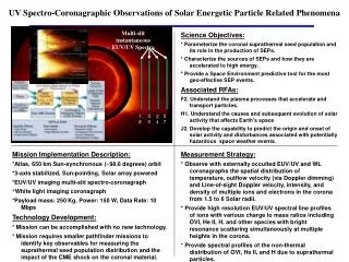
Radiation Hazards in Deep Space • Astronauts traveling in interplanetary space or working on the surface of the moon are subject to radiation exposure from high energy charged particles of both galactic and solar origin. • The galactic cosmic rays provide a continuous radiation background of very high energy particles that are difficult to shield. Fortunately their flux is relatively low. • The flux of solar energetic particles (SEPs) is typically low but not infrequently can rise rapidly to very high levels that pose a serious hazard for unprotected astronauts. There are currently no reliable methods for predicting the onset and magnitude of SEP events.
Predicting SEP Events • SEP events have their origin in the explosive release of magnetic energy in solar flares and coronal mass ejections (CMEs). • The CME explosion is released by the reconnection of stressed magnetic fields, with the reconnection occurring in the region where the magnetic field is the controlling factor. • The interaction of the outward propagating shock front of the CME with the solar wind accelerates the population of energetic particles that form the SEP event. • Depending on the details of the acceleration processes and the magnetic connectivity between the flare site and the observer the energetic particles can arrive in times ranging from less than an hour to days. • Reliable prediction of SEP events requires reliable prediction of the initial event, the shock acceleration processes and the propagation through interplanetary space. Predicting the initial explosion requires improved knowledge of the magnetic field at the reconnection site
The Reconnection Site Magnetic Field • Vector magnetic field measurements of the magnetically controlled region surrounding the reconnection site are essential to understanding the structure and dynamics of the field that creates the conditions that allows the reconnection process to occur. • Vector field measurements above the photosphere are required to determine the field at the reconnection site and to improve calculation of the magnetic free energy. • Current observations of the solar vector magnetic field are restricted to the photosphere where the gas pressure controls the behavior of the magnetic field. To understand reconnection it is essential to directly measure the magnetic field in the magnetically controlled layers above the photosphere.
The Magnetic Field and the Solar Atmosphere Because the atmospheric plasma pressure falls off more rapidly with height than the magnetic pressure there is a regime change from convectively dominated (β>1, non-force free), to magnetically dominated (β<1, force free) with a β ~1region in between.
Measuring the Magnetic Field • Solar magnetic fields are observed by measuring the polarization of magnetically sensitive spectral lines. Although the polarization from the line of sight component is relatively strong the polarization that results from the transverse components is weak, making its measurement difficult. • The sensitivity of the line of sight component is proportional to the square root of the number of photons, while that of the transverse component is proportional to the fourth root. • The lines that we propose to sample the solar atmosphere from the photosphere to the base of the corona are: FeI(6302Å), NaI(5895Å), CaII(8542Å), MgII(2880Å) and CIV (1550 Å). • We are preparing to study the polarization properties of the MgII and CIV lines using a sounding rocket payload SUMI, the Solar Ultraviolet Magnetograph, that will fly in late 2006. SUMI will make exploratory observations of the of the two lines with the objective of recovering magnetic field information.
SUMI: A Solar Ultraviolet Magnetograph SUMI is a sounding rocket instrument that will make its first flight next year that will make the exploratory observations of the magnetic field structure in the transition region.
To measure the magnetic field across the reconnection region, from the photosphere to the base of the corona, requires a large optical telescope. MTRAP, the Magnetic Transition Region Probe, is a conceptual design for a very large solar observatory that meets these requirements.
MTRAP Design Requirements • The telescope collecting area was set at 20m2 in order to obtain reasonable transverse field sensitivity at CIV. Vector magnetic field detection thresholds are: • Longitudinal Transverse • Photosphere 1G 15G • High Chromosphere 3G 100G • Low Transition Region 15G 300G • The telescope FOV is baselined at (5 x 5 arc minutes²) to cover a large active region. The angular resolution is 0.05 arc sec or 35 km (0.025 arc sec pixels). The FOV was set by the requirement to keep the energy flux density on the heat stop to the equivalent of one sun. • Integration times vary from 1-10s in the photosphere/low chromosphere to10-100s in the high chromosphere low transition region. • The strawman design has four imaging magnetographs (IM) and two spectrographs. The IMs are baselined with 4(4k x 4k) multiport readout CCDs mounted in a square array. The CCDs require large full well depths (250Ke) to minimize the number of readouts required to achieve a signal to noise of 104.
An Isometric View of MTRAPfrom a study performed by the GSFC Instrument Synthesis and Analysis Laboratory-December 2004 Secondary Mirrors and Alignment Mechanisms Field Stop Plate and Radiators 20m ADAM Extendable Mast 4 ½ m ABLE Telescoping Mast Primary Mirrors x 6 The double mast structure is necessary to allow the light from the primaries to pass from the outside to the inside of the boom where the secondary mirrors are located. The stand for the 4 ½m mast doubles as the radiator for the field stop. Spacecraft Instrument Section
MTRAP in Fairing • Payload mass estimate 1936 kg, which provides a 30 % contingency • Power estimate 800 W Telescoping ABLE mast, 2.4 meters diameter, 0.9 meters stowed, 4.5 meters deployed Mechanisms (0.5 meters high) Elephant stand (1 meter high, interface between ADAM mast and field stop platform) Primary mirror (one of 6) ABLE ADAM Mast (2.4 meters stowed; 20 meters deployed; behind primary mirrors Instruments 2.8 m diameter x 1.5 m high S/C 2.8 m diameter X 1.1 m high Diagram from Mick Correia and Joseph Generie
SUMMARY • The combination of new observations (Solar-B, SUMI, SDO, MTRAP) and improved analytical and theoretical techniques for describing the stressed magnetic field structure will improve our understanding of the processes that lead to reconnection. • If the events leading to reconnection follow a general pattern, it will be possible to develop a predictive capability that would provide warnings of hours to days of the onset and magnitude of the predicted event. • Once the events leading to a reconnection event are well understood, more modest instrumentation designed specifically to search for this signature can be developed.