Download
1 / 34
340 likes | 480 Vues
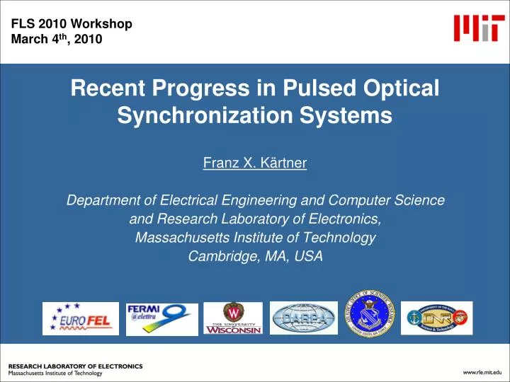
Recent Progress in Pulsed Optical Synchronization Systems. Franz X. Kärtner Department of Electrical Engineering and Computer Science and Research Laboratory of Electronics, Massachusetts Institute of Technology Cambridge, MA, USA. Acknowledgement. Students Hyunil Byun Jonathan Cox

E N D
Recent Progress in Pulsed Optical Synchronization Systems Franz X. Kärtner Department of Electrical Engineering and Computer Science and Research Laboratory of Electronics, Massachusetts Institute of Technology Cambridge, MA, USA
Acknowledgement Students Hyunil Byun Jonathan Cox Anatoly Khilo Michelle Sander Postdocs: J. Kim (KAIST, Korea) Amir Nejadmalayeri Noah Chang Colleagues and Visitors: E. Ippen, J. G. Fujimoto, L. Kolodziejski, F. Wong and M. Perrott DESY: F. Loehl, F. Ludwig, A. Winter
Outline • Synchronization System Layout for Seeded FEL • Advantages of a Pulsed Optical Distribution System • Low Noise Optical Master Oscillators • Timing Distribution Over Stabilized Fiber Links • Optical-to-Optical Synchronization • RF-Extraction and Locking to Microwave References • Prospects for sub-fs timing distribution
Seeded X-ray Free Electron Laser Long-term sub-10 fs synchronization over entire facility is required.
Seeded X-ray Free Electron Laser J. Kim et al, FEL 2004.
TR = 1/fR time … ... fR 2.fR N.fR frequency Why Optical Pulses (Mode-locked Lasers)? • Real marker in time and RF domain, every harmonic can be extracted at the end station. • Suppress Brillouin scattering and undesired reflections. • Optical cross correlation can be used for link stabilization or for optical-to-optical synchronization of other lasers. • Pulses can be directly used to seed amplifiers, EO-sampling, …. • Group delay is directly stabilized, not optical phase delay. • After power failure system can auto-calibrate.
200 MHz SolitonEr-fiber Laser • 200 MHz fundamentally mode locked soliton fiber laser • 167 fs pulses • 40mW output power K. Tamura et al. Opt. Lett. 18, 1080 (1993). J. Chen et al, Opt. Lett. 32, 1566 (2007). Similar lasers are now commercially available!
Semiconductor Saturable Absorber Modelocked 100MHz - 1GHz Er-fiber Lasers 5”x4”x1.5” out pump Long term output power with 270mW pump Optical spectrum RF spectrum • Compact, long-term stable femtosecond laser source at GHz reprate • SBR burning problem solved by SMF buffer and pump-reflective coating on SBR • 380mW pump 27.4mW output • Optical spectrum FWHM: 17.5nm • Pulse width: 187fs • Repetition rate: 967.4MHz • Intensity noise: 0.014% [10Hz,10MHz] Autocorrelation
Sensitive Time Delay Measurements byBalanced Optical Cross Correlation
Single-Crystal Balanced Cross-Correlator Type-II phase-matched PPKTP crystal Reflect fundamental Transmit SHG Transmit fundamental Reflect SHG J. Kim et al., Opt. Lett. 32, 1044 (2007)
Single-Crystal Balanced Cross-Correlator 80 pJ, 200 fs 1550nm input pulses at 200 MHz rep. rate In comparison: Typical microwave mixer Slope ~1 mV/fs @ 10GHz
ML Fiber Laser Timing Jitter Measurement Single crystal balanced cross- correlator PBS RF-pectrum analyzer Modelocked Laser 1 Modelocked Laser 2 Oscilloscope HWP Loop filter J. Kim, et al. , Opt. Lett. 32, 3519 (2007).
Timing Jitter in 200 MHz Fiber Lasers Measured Jitter Density Integrated Jitter Theory Noise Floor Ultralow timing jitter (<1 fs) in the high frequency range [100 kHz, 10 MHz] J. Kim, et al., Opt. Lett. 32, 3519 (2007).
Timing-Stabilized Fiber Links Fiber link ~ several hundreds meters to a few kilometers PZT-based fiber stretcher isolator Mode-locked laser Timing Comparison Faraday rotating mirror Cancel fiber length fluctuations slower than the pulse travel time (2nL/c). 1 km fiber: travel time = 10 μs ~100 kHz BW
2 Link Test System J. Cox et al. CLEO 2008.
Experimental Apparatus ~300 m optical fiber Piezo stretcher EDFA 200 MHz Laser In-Loop PPKTP Out-of-Loop PPKTP Invar Board Motor
Balanced Cross-Correlation Signals Link 1 Link 2 Out of Loop
Results – Timing Jitter 360 as (rms) timing jitter from 1 Hz to 100 kHz 3.3 fs (rms) timing jitter from 35 μHz to 100 kHz Out-off loop jitter limited by quantum noise
Spanning over 1.5 octaves Ti:sapphire Laser + Cr:Forsterite Laser Cr:forsterite Ti:sapphire 30 fs 5fs
Sub-femtosecond Residual Timing Jitter Balanced optical cross-correlator based on GDD (T. Schibli et al, OL 28, 947 (2003)) Long-term drift-free sub-fs timing synchronization over 12 hours J. Kim et al, EPAC 2006.
Optical-to-RF Conversion orOptical-to-RF Lockingnecessary forLocking OMO to RMO
TR/n t … ... fR 2fR nfR RF frequency Direct Extraction of RF from Pulse Train E. Ivanov et al, IEEE UFFC 52, 1068 (2005). IEEE UFFC 54, 736 (2007). AM-to-PM conversion, Temperature drift of photodetectors and mixers … TR = 1/fR time Photodetector
TR/n t … ... fR 2fR nfR RF frequency Direct Extraction of RF from Pulse Train 55 fs drift in 100 sec A. Bartels et al, OL 30, 667 (2005). TR = 1/fR time Photodetector More in: B. Lorbeer et al, PAC 2007.
Balanced Optical-Microwave Phase Detector(BOM-PD) Microwave Signal Electro-optic sampling of microwave signal with optical pulse train J. Kim et al., Opt. Lett. 31, 3659 (2006).
Optoelectronic Phase-Locked Loop (PLL) Regeneration of a high-power, low-jitter and drift-free microwave signal whose phase is locked to the optical pulse train. Balanced Optical-Microwave Phase Detector (BOM-PD) Regenerated Microwave Signal Output Tight locking of modelocked laser to microwave reference Balanced Optical-Microwave Phase Detector (BOM-PD) Modelocked Laser Stable Pulse Train Output
Testing Stability of BOM-PDs BOM-PD 1: timing synchronization BOM-PD 2: out-of-loop timing characterization
Long-Term Stability: 6.8 fs drift over 10 hours RMS timing jitter integrated in 27 μHz – 1 MHz: 6.8 fs J. Kim et al, Nature Photonics 2, 733 (2008).
Delay Locked Looop: 2.9 fs drift over 8 hours RMS timing jitter integrated in 0.1 Hz – 1MHz, 2.4 fs J. Kim et al, submitted to CLEO 2010.
1 GHz diode pumped CrLiSAF Laser: Modelocked Jointly with Jim Fujimoto
Prospects for Attosecond Timing Distribution (100 MHz Cr:LiSAF Laser, SSB scaled to 1GHz) U. Demirbas, submitted to CLEO 2010
Conclusions • Long term stable (10h) sub-10 fs timing distribution system is completed. • True long term stability (forever): Implement Polarization Control • Master Oscillators commercially available + amplifier >400mW of • output power > 10 links) • 300 m Fiber Links, over 10h < 5 fs ( < 1fs possible) • Optical-to-Optical Synchronization, over 12h < 1fs • Optical-to-Microwave Synch., over 10h < 7fs ( < 1fs possible) • Solid-State Lasers show timing jitter [1kHz – 10 MHz] < 200as (<50as) • Continued development of this technology seems to enable < 100as long term stable timing distribution.