Download
1 / 30
300 likes | 303 Vues
This presentation explores the development of CEF networks design, discussing legacy processes and new approaches, such as the procurement of dark fibers and multi-vendor equipment integration. It highlights the importance of optical technology and the role of fibers as key building elements in network design.

E N D
Development of CEF networks design Stanislav Sima Lada Altmannova Prague May 17th, 2005
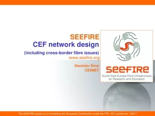
Previous presentations available on-line I. Development of the CESNET2 optical network. TERENA Networking Conference, Limerick, June 4, 2002. (Nothing-In-Line approach + 189 km NIL operation announced) http://www.terena.nl/conferences/tnc2002/Slides/sl3c2.ppt Long distance fiber connections in NREN, TF-NGN Budapest, October 18, 2002. (10 Gb/s NIL possible up to about 300 km, single fibre bi-directional transmission in production network up to 125 km) http://www.terena.nl/tech/task-forces/tf-ngn/presentations/tf-ngn9/sima.ppt Fibres and advanced optical devices for a new networking strategy. TERENA TF-NGN Cambridge, September 16th, 2003. (Fibre is strategic asset. CEF networks concept. Free space optics for cost-effective first mile. Connect Near over Border by fibre.) http://www.terena.nl/tech/task-forces/tf-ngn/presentations/tf-ngn12/20030915_SS_Optical.pdf Development of CEF networks design
Previous presentations available on-line II. Procurement and lighting of dark fibre. CEF Networks workshop, Prague May 2004. (Double payment of fibre infrastructure? NIL results. CESNET-made optical amplifiers deployment announced.) http://www.ces.net/doc/seminars/20040525/pr/CEF%20Networks3ext.ppt Towards a Nation-wide Fibre Footprint in research and education networking. TERENA Networking Conference, Rhodes, June 9, 2004. (Dark fibres brings progress to REN design and subsequently to WAN design generaly. From naive economy to strategy. National fibre footprint in European NRENs. GLIF and CzechLight.) http://www.terena.nl/conferences/tnc2004/programme/presentations/show.php?pres_id=97 Development of CEF networks design
Network design • Specifications of three items are needed: • Network services, • building elements, • implementation (deployment, setup, …) • Top-down design process starts with network services specification, botom-up design process starts with building elements specification • Neither of above two start points is „the best“ !!! • Results of one way design are suboptimal (i.e. bad), returns and corrections of decisions in design process are needed !!! • Experience and theoretical knowledge of circuits design and computer design help to deeply understand above problem Development of CEF networks design
Legacy in network design • Buiding elements, implementation and operation of large scale networks are procured • Procurement is long process (especially if public funding is used): e.g. 7-24 month • Returns and corrections of decisions are very difficult or impossible in procurement process • Vendors have limited possibilities to tailor services and equipment to user needs, so they offer „universal solution“ (=suboptimal for given case) • Exceptions: • legal system in some countries is not so restrictive to research • lower scale networks (e.g. Metropolitan) make implementation and operation by own staff Development of CEF networks design
Development of network design • Legacy design proces often gives suboptimal network services (costs, rate, flexibility…): mainly transmission layer is poorly designed from technical and economical point of view (is the most hidden to user) • In general, improvement possibilities were proved: • procurement of dark fibres instead services • procurement of multivendor equipment plus integration • Necessity of bad reliability and interoperability was not proved • Multidomain operation is needed generaly and includes multivendor interoperability and multidomain monitoring and control • Disadvantage: design and operation are more complicated • Solution: procure support of design, implementation and operation, and save own ability to quick return and correct design (including retendering etc.) Development of CEF networks design
New situation in network design • Main source of innovation is optical technology now • Fibres are the most important buiding element now • Change of P2P services by P2P fibres was first step only • New transmitters, receivers, amplifiers, gratings etc. are available, some of they even with MultiSource Agreements • CEF Networking enables high availability and cost-efectivness of new services (e.g. Facilities based networking, E2E lightpath on demand, fibre switching…) • CEF approach starts in WAN or MAN in companies, corporates, military, municipalities and hospitals (etc.): new market segment is emerging, tasks of vendors are changing Development of CEF networks design
CESNET2 fibre procurement • Re-tendering since 2001 to 2005, goals: • decreasing costs, including single fibre lines • shorter lines including first mile • NIL approach • two or more fibre pairs to network node • reliability increase by physical diversity of first miles to node • single provider of dark fibre line (spans could have different owners) • first mile for international lines in Prague • first mile for fibre connection of user premises • cross border fibres (single provider) Development of CEF networks design
DF Lines • 3 500km of fibre pair operational in CESNET2 • 350km of single fibre within CESNET2 • 660km of fibre pair in CzechLight testbed • More than 760km of special fibres on the spools in laboratory Development of CEF networks design
Example of lambdas and fibres costs(fibres are blue, road distances of cities are from 20 to 210 km) Development of CEF networks design
Cross border fibre (CBF, NoB) • Viena-Bratislava-Brno-Ostrava-BialskoBiala • Austria-Slovakia-Czech Rep-Poland • Our presentation of experience with CBF on TF-NGN Cambridge, September 2003 (we call it NoB, Near over Border) • SERENATE study in 2003 – we request analysis • Having NoB fibre connection, you could implement some lambdas for GEANT2 (or for Abilene in US.) • Cost rule for fibres is KIS (keep it short). • GN2 tender allowing fibres continues (we will use examples, not results) • NoB is supported by SEEFIRE study Development of CEF networks design
2 years after: Analysis still needed • SERENATE study, p.24, published April 22., 2003 http://www.serenate.org/publications/d9-serenate.pdf • „Prices of equipment are relatively important for the economics of transmission systems, but the overall costs heavily depend on the network architecture and topology. The basic approach is to connect geographically neighbouring universities by fibres. NRENs should carefully analyse the pros and cons of any solution going beyond this, i.e. using an overlay fibre structure, because such a solution is usually more expensive. It would be feasible and cheap, albeit not simple, to independently cross national borders to build regional fibre networks.“ • „This situation requires a new and careful analysis of the architecture and topology of the transmission layer (typically a transmission structure overlaying the NREN’s topology) at the European level.“ Development of CEF networks design
Overlaying fibre lines: when are needed??(lines are examples only) Development of CEF networks design
Facility based networking: GLIF and CzechLight Global Lambda Integrated Facility (GLIF) • Environment for co-operation: networking, infrastructure, network engineering, system integration, middleware, applications • GLIF was established by invited participants at the 3rd Global Lambda Grid Workshop, held August 27, 2003 in Reykjavik, Island, www.glif.is • Dark fibres are often used for Gigabit or 10 Gigabit access to cities and university premises Development of CEF networks design
Facility and production networking • Facilility and production networking should be complementary • Prague-Amsterdam 10 Gb/s lambda since September 1, 2004 (Cisco-Lucent-Nortel) • We are studying/testing possibilities of lambda connection to FermiLab, RAL, Karlsruhe, Taipei etc. • We will use E2E lambdas prepared by GEANT2+NREN+MAN, if (when) available for such connections Development of CEF networks design
GLIF – World Map December 2004 Development of CEF networks design
CzechLight connections (to GLIF, to GN2 testbed and to cz premises) Development of CEF networks design
CzechLight intercity connections • Prague – Amsterdam lambda (GLIF facility), first mile in Prague on dark fibre, OC-192c transmission, grey 1550nm • Prague – Brno, dark fibre, 298.3 km, 66,5 dB, including 257.3 km of G.655 fibre, DWDM OC-192c transmission, NIL test • Prague – Plzen, dark fibre, 159.4 km, 36.7 dB, GE transmission by CzechLight EDFA 2in1 Development of CEF networks design
CzechLight connections in Prague region Connections of Particle physics workplaces - Institute of Physics of the Academy of Sciences of theCzech republic, dark fibre, GE transmission - Faculty of Mathematics and Physics of Charles University, dark fibre, GE transmission - Nuclear Physics Institute of the Academy of Sciences of the Czech Republic in Řež, dark fibre, GE transmission - Faculty of Nuclear and Physical Engineering of Czech Technical University, lambda on PASNET dark fibres by CWDM, GE transmission We prepare connections for medical research Development of CEF networks design
City dark fibre lines to the of CzechLight node in Prague Development of CEF networks design
CzechLight configuration • Core node in Prague Cisco 15454 with 10 G DWDM SONET, 4xGE Cisco C3550 – 12G Cisco C6503 with 10 GE and GE • Core node in Brno Cisco 15454 with 10 G DWDM SONET, 4xGE • Cisco 6506 with 10 GE and GE prepared Development of CEF networks design
Acknowledgement • Jan Gruntorad for support • Miroslav Karasek, Jan Radil and Josef Vojtech for advanced lighting of CESNET2 and CzechLight fibres • Comment: presented ideas and opinions are result of our ongoing R&D activities and are opened to improvement Development of CEF networks design