Download
1 / 31
310 likes | 573 Vues
Selected Aspects of Hybrid MR-PET Imaging. Uwe Pietrzyk Institute of Neurosciences and Medicine (INM-4) Medical Imaging Physics / PET Detector Technology Research Center Juelich & Department of Mathematics and Natural Sciences University of Wuppertal Germany. Topics:

E N D
Selected Aspects of Hybrid MR-PET Imaging Uwe Pietrzyk Institute of Neurosciences and Medicine (INM-4) Medical Imaging Physics / PET Detector Technology Research Center Juelich & Department of Mathematics and Natural Sciences University of Wuppertal Germany
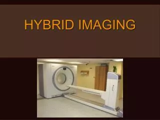
Topics: • What is Hybrid Imaging? • Basic Elements of Medical / Biomedical Imaging • How Image Fusion stimulated Hybrid Devices like SPECT/CT & PET/CT • Challenges in Combining MR + PET = MR-PET • Configurations in Operation
What is Hybrid Imaging? Whenever we consider to combine two different modalities, we call the result a hybrid imaging device: SPECT/CT, PET/CT, PET/MRI (or MR-PET), SPECT/MRI, PET or SPECT / Optical Imaging Systems, X-ray- Fluoroscopy / MRI, Photoacoustic Tomography, Optical / MRI & Appropriate smart probes !! Paradise for Photo Detectors !! Result: Combined Information / Fused Images (Inspired by: S. Cherry, Semin Nucl Med 2009; 39:348-353)
The Basic Principle of Imaging Source (external) Object (+ Source) Selection / Definition using:(a) Diaphragm/Aperture; (b) Grid; (c) Collimator;(d) Coincidence Circuit) Detector X ✓
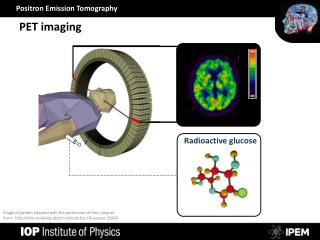
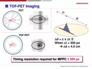
Basics in Positron-Emission-Tomography (I) Detector Detector MRI NoteTwo co-linear photons No collimation!Need correction for scatter and attenuation!Unknown tracer-distribution in an environment of unknown denstity 5
Basics in Positron-Emission-Tomography (II) • Imaging System Components: • Detector high resolution and high sensitivity • Scintillators (LSO / GSO, ...) PMT or APD fast electronics • highly specifictracers, „smart probes“; • nano molar concentrations • suitable isotope: 18F (T1/2 109.8 min, avg. Ekin0.242 MeV, • range: FHWM 0.22 mm ) • precise image reconstruction incl. corrections MRI 6 6 6
photomultipliers scintillator A B B D g (511 keV) Basics in Positron-Emission-Tomography (III) (a) 1×1×10mm LSO crystals, (b) polyurethane grid and (c) completed 12 × 12 scintillator array. MRI
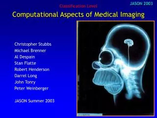
Fundamental Difference Bridged by Hybrid devices & Image Fusion! Functional Imaging PET and SPECT NuclearMedicine: PET = Positron Emission Tomography SPECT= Single Photon Emission ComputedTomography Structural Imaging CT and MRI Radiology: CT= X-Ray Computed Tomography MRI= Magnetic Resonance Imaging
Aspects of Fusing Multimodality Image (I) Structure without Function is a Corpse ... Function without Structure is a Ghost (Stephen Wainwright) (from: D.W. Townsend, Dual-Modality Imaging: Combining Anatomy and Function, J Nucl Med 2008; 49:938-955) Image Fusion ... is to give Life back to the Corpse and show the Ghost where it comes from
Aspects of Fusing Multimodality Image (II) Image Fusion – expectation ~20 Years ago (~1991) ... Software based Image Fusion will guide us to what we would like to see as hybrid imaging devices ... Image Fusion – reality today (2011) ... Software based Image Fusion has guided us to what we now see as hybrid imaging devices ... Note: We always apply Software to obtain „Fused Images“!!
Data from Different Systems: need software to register and fuse images (I) PET CT Image Fusion MRT SPECT 11
Data from Different Systems: need software to register and fuse images (II) S u c c e s s of software based registration in brain studies has promoted hardware based fusion! F a ilure of software-based registration in extra-cranial studies(motion and displacement of organs) has promoted dual-modality systems! MRI-guided PET (~1994) 12
Images from Hybrid Systems: Sequential Acquisitions PET PET/CT CT Image Fusion SPECT/CT MRT-PET MRT SPECT 13
Images from Hybrid Systems: Sequential Acquisitions (PET/CT) 14 [D.W. Townsend, J Nucl Med 2008; 49:938-955]
Typical Application for PET/CT Fusion CT • Highly specific tracer • Focal uptake 80 MBq, 4h pi, 6 min / bed position (M Hofmann) 68Ga-DOTATOC BUT: PET/CT is not truly simultaneous -> Danger of movement -> artefacts in quantitative PET images
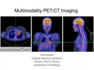
Images from Hybrid Systems: Simultaneous Acquisitions PET CT Image Fusion MRT-PET MRT SPECT 16
Complementary Devices: Hybrid Imaging with MRI-PET Note: Already today, PET is mostly available as a combined modality, namely PET/CT 17
Current Developments for PET (1) LSO PMT: Size:10-50 mm Gain: up to 106 Risetime: 1 ns QE: 20 % Classic solution: Scintillator + PMT APD: Size:5x5 mm2 Gain: up to 200 Risetime: 5 ns QE: 60 SiPM: Size:5x5 mm2 Gain: 105-106 Risetime: 1 ns QE: 30% LSO Modern solution: Scintillator + APD / SiPM More Compact! 18
Current Developments for PET (2) APD Hamamatsu 4x8 elements 10.5x20.7 mm2 pixelized scintillator block monolithic scintillator block • more compact PET • much less “dead space” • higher sensitivity 19
detector module 6-module cassette (32 cassettes) patient bed gantry head coil bed rails Scanner size: 36cm dia. x 20cm FOV Siemens Current MR-PET Design for Brain Imaging
MR-BrainPET: Major PET-Components PET insert new integrated detector block gantry RF shield 33 mm x 33 mm x 63 mm phantom head coil
BrainPET in a 3T-MRI-scanner Siemens MAGNETOM Trio Detector: 12x12 LSO crystals 2.5 x 2.5 x 20 mm3 Readout: 3 x 3 APDs (Hamamatsu) Resolution (FWHM, mm) : r = 0 cm 2.5 cm 5 cm Tangential: 2.3 2.4 2.0 Radial 2.0 2.4 3.3 Z-Direction 2.5 3.1 H. Herzog, Jülich Still need to get the attenuation map in MR-PET Imaging!!! MRI
Emission measurement Transmission measurement Rotatingline sourcefilled with 68Ge The detector measures PE = ò A(x,y) dl * exp( - ò µ (x,y) dl') The detector measures AF = exp( - ò µ (x,y) dl') Correction for Photon Attenuation Classic approach for stand-alone PET: PEcorr = PE / AF = ò A(x,y) dl Approach for PET/CT: AF calculated from CT-values!!
Simultaneous MR-BrainPET measurement of a brain tumor after injection of [18F]-FET HR+: 40-50 min p.i. T1-MPRAGE BrainPET: 55-85 min p.i.
Mutual Influence in MR-PET – a Challenge for Quantitative Imaging ??!! Count Rate = f(Time, Sequence) MPRAGE FLAIR UTE EPI Count rate: - 2%
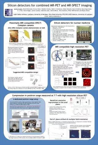
Wall MR-PET Design for Whole Body Applications PET ring inside gradient: • Easy removal of PET ring for maintenance and repair • Higher S/N for PET • Annihilation photons need only traverse RF coil --> minimal scatter • Gradients need more current • Stronger coupling of RF coil Schwaiger, Ziegler et al., 2005
MR-PET Design for Whole Body Applications Courtesy: Sibylle Ziegler, TU Munich, Fall 2010)
MR-PET Design for Whole Body Applications Courtesy: Sibylle Ziegler, TU Munich, Fall 2010)
Finally: Why we really need good energy resolution!! • Decay scheme of I-124: • - Separate g-Lines: • - additional Emission to • e+-Annihilation • - 602,7 keV-Line dominant (63%) • & within standard Energy • Window (250 bis 750 keV) • e+-Emission: 22,54% • (11,72% in Coincidence • with 602,7 keV-Line) [3] [3] http://www.nndc.bnl.gov/nudat2/ dE/E=15 % dE/E=5 % GATE-Simulations by Sophie Sauerzapf Uni Freiburg
Acknowledgements Special thanks to Markus Axer (INM-1, FZ-Juelich, University Wuppertal) Jürgen Scheins (INM-4, FZ-Juelich) Sophie Sauerzapf (Nuclear Medicine, University of Freiburg) Lena Thomas (University of Frankfurt) Karl Ziemons (FH-Aachen/Juelich) Hamid Zakhnini (FZD & University of Wuppertal) Hans Herzog (INM-4, FZ-Juelich) Christoph Parl (ZEL, FZ-Juelich) Matthias Streun (ZEL, FZ-Juelich) & all Members of the Crystal Clear Collaboration & all Members of the OpenGATE Collaboration 30
Contact Prof. Dr. Uwe Pietrzyk (Physicist) Institute of Neurosciences and Medicine (INM-4)Medical Imaging Physics Group Leader: PET Detector Technology Research Center Juelich GmbH, Germany E-Mail: U.Pietrzyk@fz-juelich.de http://www.fz-juelich.de/INM & Department of Mathematics and Natural Sciences University of Wuppertal, Germany 31