Download
1 / 19
190 likes | 195 Vues
Radiation tolerance of commercial 130nm technologies for High Energy Physics Experiments. Federico Faccio CERN/PH-MIC. P+ guardring. Enclosed Layout Transistor (ELT). Foreword: HBD in 0.25 m m CMOS. TID-induced effects:. Solutions:. Foreword: Foundry Service.

E N D
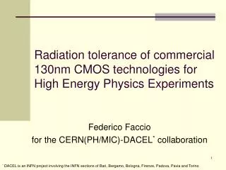
Radiation tolerance of commercial 130nm technologies for High Energy Physics Experiments Federico Faccio CERN/PH-MIC
P+ guardring Enclosed Layout Transistor (ELT) Foreword: HBD in 0.25mm CMOS TID-induced effects: Solutions: F.Faccio
Foreword: Foundry Service • Technology used: 0.25mm CMOS • MPW service organized for more than 100 different ASICs • More than 20 different designs in production (some are multi-ASIC) • More than 2000 wafers (8-inch) produced! F.Faccio
Outline • Motivation • TID1 test structure and measurement setup • NMOS and PMOS results • FOXFETs results • SEE results • Conlcusion F.Faccio
1965: Number of Integrated Circuit components will double every year G. E. Moore, “Cramming More Components onto Integrated Circuits”, Electronics, vol. 38, no. 8, 1965. 1975: Number of Integrated Circuit components will double every 18 months G. E. Moore, “Progress in Digital Integrated Electronics”, Technical Digest of the IEEE IEDM 1975. 1996: The definition of “Moore’s Law” has come to refer to almost anything related to the semiconductor industry that when plotted on semi-log paper approximates a straight line. I don’t want to do anything to restrict this definition. - G. E. Moore, 8/7/1996 P. K. Bondyopadhyay, “Moore’s Law Governs the Silicon Revolution”, Proc. of the IEEE, vol. 86, no. 1, Jan. 1998, pp. 78-81. Motivation F.Faccio
TID1 test structures and measurement setup • Integrated in MPW run May2004 • NMOS and PMOS transistors, core and IO devices (different oxide thickness), FOXFETs • Rows of pads for testing at probe station – no bonding required • Irradiation with X-rays at CERN up to about 140Mrad, under worst case static bias F.Faccio
Core NMOS transistors, enclosed layout (ELT) • The radiation hardness of the gate oxide is such that practically no effect is observed up to 140Mrad F.Faccio
Core NMOS transistors, linear layout (1) • When the transistor is off or in the weak inversion regime: • Leakage current appears (for all transistor sizes) • Weak inversion curve is distorted F.Faccio
Core NMOS transistors, linear layout (2) • When the transistor is in the strong inversion regime: • An apparent Vth shift (decrease) for narrow channel transistors • The narrower the transistor, the larger the Vth shift (RINCE) • Above W of about 0.8-1mm the effect is practically negligible F.Faccio
E field lines E field lines Polysilicon Polysilicon gate gate - - + + + + ID - - + + + + STI STI - + + - + + STI STI Oxide trapped charge Interface states Depletion region Depletion region Main transistor Lateral parasitic transistor 0 VGS Radiation-induced edge effects - NMOS F.Faccio
Core NMOS transistors, linear layout (3) • Comparing with enclosed transistors, it appears that all effects on linear transistors are due to edge effects • A “peak” damage dose exists • Peaking will depend on dose rate and temperature, difficult to forecast precisely F.Faccio
Core PMOS transistors, linear layout (1) • No change in the weak inversion regime, no leakage • In the strong inversion regime: • An apparent Vth shift (decrease) for narrow channel transistors • The narrower the transistor, the larger the Vth shift • Above W of about 0.8-1mm the effect is practically negligible F.Faccio
E field lines E field lines Polysilicon Polysilicon gate gate - + + + + + ID + - + + + + STI STI + + + + + + STI STI Oxide trapped charge Interface states Depletion region Depletion region Main transistor Lateral parasitic transistor 0 VGS Radiation-induced edge effects - PMOS F.Faccio
Core PMOS transistors, linear layout (2) • There is no peak here, but a continuous shift of Vth • The effect is more pronounced for narrow transistors F.Faccio
FOXFETs (isolation test) • FoxFETs are “Field Oxide Transistors” • Good to characterize isolation properties with TID • Source-Drain could be either Nwells or n+ diffusions F.Faccio
FOXFETs • Also in this case, a « peak » can be distinguished (isolation oxide has similar properties to lateral oxide) • Not a problem for digital (all wells at Vdd, low level of inter-transistor leakage), but care must be used for full custom to avoid large effects F.Faccio
SEE results: the SRAM circuit • 16kbit SRAM test circuit designed using the SRAM generator from a commercial library provider – not dedicated rad-tolerant design! • Test circuit in the same prototyping run as TID1 (in May 2004) • Test performed with Heavy Ions at the Legnaro National Laboratories accelerator in June 2005 F.Faccio
Heavy Ion irradiation results • Test at Vdd=1.5 and 1.25 V, results very similar • Sensitivity to very low LET values (threshold below 1.6 MeV/cm2mg) • Comparison with 0.25mm memory (rad-tol design!!): • Cross-section 15-30 times larger in LHC environment F.Faccio
Conclusion • Natural radiation tolerance better than for the quarter micron technology • TID effects on linear transistors vary with transistor size (RINCE), dose rate and T, and peak at 1-6Mrad • TID effects on enclosed transistors (ELTs) practically not observable • More work in progress to see if this is typical of the 130nm node or rather “specific” to one vendor/foundry. Work on 130nm in collaboration between CERN and INFN Bari, Padova, Bologna, Torino F.Faccio